02/5/27 CD-XP120W(A)1.fm
E-8
ENGLISH
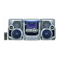
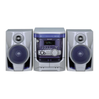
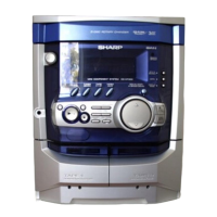
CD-XP120W
Preparation for Use
- System connections -
!
Removing the transport screw
Before turning the power on, be sure to remove the transport screw
on the back of the unit using a flat head screwdriver or a coin.
Note:
This screw is required when transporting the unit again. Please
keep it (see page 27).
!
Aerial connection
Supplied FM aerial:
Connect the FM aerial wire to the FM 75 OHMS terminal and posi-
tion the FM aerial wire in the direction where the strongest signal
can be received.
Supplied AM loop aerial:
Connect the AM loop aerial to the AM LOOP socket. Position the
AM loop aerial for optimum reception. Place the AM loop aerial on a
shelf, etc., or attach it to a stand or a wall with screws (not supplied).
Note:
Placing the aerial on the unit or near the AC power lead may cause
noise pickup. Place the aerial away from the unit for better reception.
Installing the AM loop aerial:
External FM aerial:
Use an external FM aerial if you require better reception. Consult
your dealer.
Note:
When an external FM aerial is used, disconnect the supplied FM
aerial wire.
!
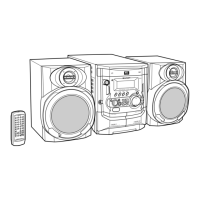
Speaker connection
Connect the wire with the white line to the minus (-) terminal and the
plain wire to the plus (+) terminal.
Caution:
Note:
The speaker grilles are not removable.
< Assembling > < Attaching to the wall >
Wall Screws (not supplied)
External
FM aerial
75 ohm
coaxial
cable
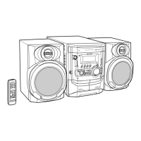
Right speaker Left speaker
"
Use speakers with an impedance of 8 ohms or
more, as lower impedance speakers can damage
the unit.
"
Do not mistake the right and the left channels. The
right speaker is the one on the right side when you
face the unit.
"
Do not let the bare speaker wires touch each
other.
"
Do not allow any objects to fall into or to be placed
in the bass reflex ducts.
"
Do not stand or sit on the speakers. You may be in-
jured.
Incorrect
Plain
White line