EasyManua.ls Logo

Sharp IQ-9200 User Manual

Sharp IQ-9200
46 pages
To Next Page IconTo Next Page
Page #1 background imageLoading...
Page #1 background image
OZ-9600
II
IQ-9200
SHARP
SERVICE
MANUAL
STANDARD
FUNCTION
10
digits
1M
DISPLAY SECTION
ELEMENT:
DISPLAY:
FSTN
LCD
320
x
240
dot
matrix
liquid
crystal
display
LSI
CPU:
LH58061M
Display:
LF7713Q
RTC:
SMC5245
POWER
SUPPLY
AG:X
DC:O
Main
power
supply:
6
Vde
Alkaline
batteries
(LRO3
x
4)
Memory
backup
power:
3
Vdc
lithium
battery
(CR2032
x
1)
POWER
CONSUMPTION
0.31
W
AUTO
POWER
OFF
TIME
12
minutes
MEMORY
PROTECT
Yes
DIMENSIONS(mm)
Open:
=
180(W)
x
210(D)
x
14.2(H)
mm.
7-3/32"(W)
x
8-9/32"(D)
x
9/16"(H)
Closed:
180(W)
x
105(D)
x
25.4(H)
mm.
7-3/32"(W)
x
4-1/8"(D)
x
1"(H)
Weight
Approx.
430g
CALCULATIONS
Functions:
addition,
subtraction,
multiplication,
division;
constant,
square
root,
percent,
memory
calculation,
date
calculation,
paperless
printer.
Digits:
10
digits
Serial
input/output
Type
of
transmission:
Asynchronoushalf-duplex/fullduplex
Transmission
speed:
300,
600,
1200, 2400,
4800,
9600
bps
Parity
bit:
even,
odd,
none
Word
length:
7
or
8
bits
Stop
bit:
1
or
2
bits
Connector
used:
15-pin
connector
Output
signal
level:
©
C-MOS
level
(4
to
6
volts)
Interface
signals:
Input;
RD,
CS,
CD, DR,
CI
Output;
SD,RS,
RR,
ER
Other;
.SG,
VC,
FG
Operating
temperatures
0°C
to
40°C
(32°
to
104°F)
Peripherals
and
transfer
interface
IR
transfer
Up
to
a
distance
of
approx.
80
cm.
Cable
jack
15-pin
IC
card
slot
1
Parts
marked
with
"A\”
is
important
for
maintaining
the
safety
of
the
set.
Be
sure
to
replace
these
parts
with
specified
ones
for
maintaining
the
safety
and
performance
of
the
set.
SHARP
CORPORATION
CODE:
00Z0Z96002SME
OZ-9600II
mopeL
1Q-9200
Electronic
Organizer
notebook
section
.
Applications
Calendar,
Schedule,
To
Do,
Anniversary,
Telephone,
User
File,
Notebook,
Outline,
Scrapbook,
Filter
Memory
capacity
512
Kbytes
(User
area:
Approx.
381
Kbytes)
Schedule
application
capacity:
:
Approx.
6,730
entries
consisting
of
an
averge
of
32
charactes
Tel
application
capacity:
Approx.
6,610
entries
consisting
on
averge
of
16
charactes
in
the
name
field
and
12
in
the
number
field
These
capacities
only
apply
when
all
the
available
memory
is
committed
to
a
single
function.
Maximum
Notebook:
16
Kbytes
data
size
per
Outline:
32
Kbytes
for
an
entire
outline
entry
2
Kbytes
for
each
topic
Tel/User
File:
2
Kbytes
for
text
data
61.7
Kbytes
for
graphics
data
Other
applications:
2
Kbytes
User
interfaces
Touch
panel,
keyboard
Other
features
Secret
function,
data
transfer,
search
Clock
Crystal
oscillation
frequency:
32,768
Hz
Clock
precision:
Average
variance
per
day,
1.5
seconds
(at
25°C/77°F)
Content
of
displays:
year,
month,
day,
day
of
week,
hours,
minutes,
A.M./P.M.,
city
names
:
Time
system:
12-hour
and
24-hour
clock
World
clock
function:
Display
of
date
and
time
for
the
world’s
cities.
Enable/dis-
able
daylight
saving
time
display
function.
Operating
time
Battery
life
may
vary
depending
on
usage.
Operating
batteries:
When
alkaline
batteries
are
used:
@
Approx.
80
hours
(2.5
months
of
1
hour
continuous
use
per
day)
Continuous
display
at
an
ambient
temperature
of
20°C
(68°F)
©
Approx.
70
hours
(2
months
of
1
hour
continuous
use
per
day)
Searching
data
for
5
minutes
and
display
on
for
55
minutes
per
hour,
at
an
ambient
temperature
of
20°C
(68°F)
The
battery
life
may
be
shorter
than
the
above
when
manganese
batteries
are
used.
Memory
backup
battery:
:
Approx.
5
years
(regardless
of
the
condition
of
the
operating
batteries)
Accessories
Alkaline
batteries
(LRO3
x
4)
Lithium
batteries
CR2032
(installed)
Touch
pen,
Operation
manual,
protection
card
This
document
has
been
published
to
be
used
for
after
sales
service
only.
The
contents
are
subject
to
change
without
notice.
Question and Answer IconNeed help?

Do you have a question about the Sharp IQ-9200 and is the answer not in the manual?

Sharp IQ-9200 Specifications

General IconGeneral
TypeElectronic Organizer
BrandSharp
ModelIQ-9200
DisplayLCD
FunctionsCalculator

Summary

KEY LAYOUT GUIDES

USA (OZ9600II) Key Layout

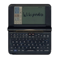
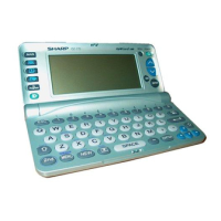
Illustrates the key layout for the US model.

UK (IQ-9200) Key Layout

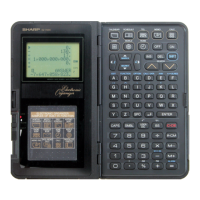
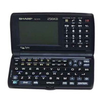
Illustrates the key layout for the UK model.

Other Regions (IQ-9200) Key Layout

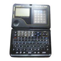
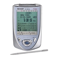
Shows the key layout for regions other than USA/UK.

SYSTEM CONFIGURATION AND HARDWARE OVERVIEW

Hardware Block Diagram

Provides a block diagram of the main hardware components.

CPU (LH58061M) DESCRIPTION AND DIAGRAM

CPU Introduction and Features

Details the CPU's introduction, process, bits, ROM, RAM, and I/O.

CPU Block Diagram

Illustrates the internal block diagram of the CPU.

CPU PIN DETAILS AND ASSIGNMENT

CPU Pin Layout

Shows the physical pin layout of the CPU.

CPU Pin Assignment and Function

Lists each pin's signal name, I/O, and function.

LCD DRIVER DESCRIPTION AND DIAGRAM

LCD Driver Block Diagram

Shows the block diagram of the segment driver.

LCD COMMON DRIVER DETAILS

Common Driver Pin Description

Lists pins and their functions for the common driver.

RTC (SMC5245) DESCRIPTION AND FEATURES

RTC Pin Description

Details the function of each pin on the RTC.

RTC Introduction and Features

Introduces the RTC and its features.

RTC Pin Functions

Explains the function of specific pin groups (data bus, address bus, etc.).

SYSTEM GATE ARRAY AND EEPROM CONTROL

System Gate Array Description

Details the brief functional description of the system gate array.

EEPROM (µPD28C64GX) FUNCTIONS AND MODES

EEPROM Functional Description

Outlines the EEPROM's data poll and write error prevention functions.

EEPROM Block Diagram and Pin Layout

Shows the EEPROM block diagram and pin layout.

EEPROM Operation Modes

Details the five operation modes of the EEPROM.

EEPROM OPERATION MODES AND MEMORY MAPPING

EEPROM Read, Standby, and Write Modes

Explains read, standby, byte write, and page write modes.

EEPROM Chip Erase and Write Inhibit Modes

Details chip erase and write inhibit modes.

EEPROM Memory Mapping

Illustrates the memory map of the device.

LCD CONTRAST AND LOW BATTERY DETECTION

LCD Contrast Adjustment

Explains how LCD contrast is adjusted.

Low Battery Detection

Describes the battery level monitoring and warning system.

SERVICING NOTES AND BATTERY REPLACEMENT

Resetting the Organizer

Provides instructions for resetting the organizer.

Battery Replacement Guidelines

Offers general guidelines and cautions for battery replacement.

BATTERY REPLACEMENT PROCEDURE

Replacing Operating Batteries

Step-by-step guide for replacing main operating batteries.

Replacing Memory Backup Battery

Instructions for replacing the memory backup battery.

EEPROM WRITING AND CHECKING PROCEDURES

EEPROM Writing Card Making Procedure

Details the procedure to create an EEPROM writing card.

EEPROM WRITING PROCESS EXECUTION

Setting Up and Executing EEPROM Writing

Describes setting up the OZ-7200/IQ-7300M and executing writing.

Checking EEPROM Writing Completion

Explains how to verify successful EEPROM writing.

EEPROM WRITING VERIFICATION AND END PROCESS

EEPROM CHECK CARD MAKING PROCEDURE

EEPROM Check Card Making Steps

Details the steps for creating the EEPROM check card.

EEPROM CHECK CARD OPERATION FLOWCHARTS

EEPROM VERSION AND OPERATION CHECK

SUB-PWB UNIT DISASSEMBLY AND REASSEMBLY

DIAGNOSTICS AND CHECK ITEMS

SYSTEM CHECK PROCEDURES

KEY CHECK AND ERROR HANDLING

MAIN PWB CIRCUIT DIAGRAM

SUB PWB CIRCUIT DIAGRAM

PARTS LIST - MAIN PWB UNIT

SUB PWB UNIT COMPONENTS DETAILS

Related product manuals