2008-03-14
LC-32A28L, LC-42A48L
53
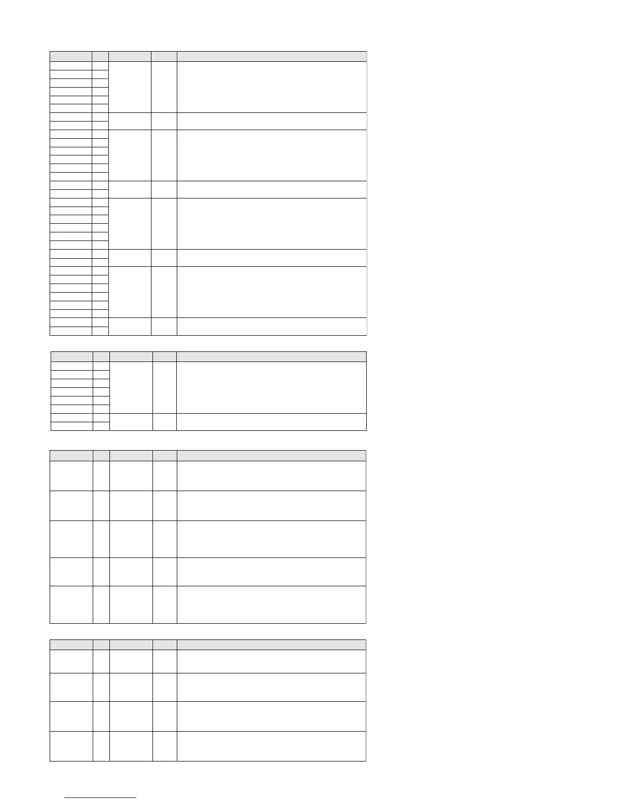
Pin Listings
HDMI Receiver
Pin Name Pin Type Dir Description
R0X0P 68
R0X0N 67
R0X1P 70
R0X1N 69
R0X2P 72
R0X2N 71
TMDS Input TMDS input Port 0 data pairs.
R0XCP 66
R0XCN 65
TMDS Input TMDS input Port 0 clock pair.
R1X0P 4
R1X0N 3
R1X1P 6
R1X1N 5
R1X2P 8
R1X2N 7
TMDS Input TMDS input Port 1 data pairs.
R1XCP 2
R1XCN 1
TMDS Input TMDS input Port 1 clock pair.
R2X0P 14
R2X0N 13
R2X1P 16
R2X1N 15
R2X2P 18
R2X2N 17
TMDS Input TMDS input Port 2 data pairs.
R2XCP 12
R2XCN 11
TMDS Input TMDS input Port 2 clock pair.
R3X0P 22
R3X0N 21
R3X1P 24
R3X1N 23
R3X2P 26
R3X2N 25
TMDS Input TMDS input Port 3 data pairs.
R3XCP 20
R3XCN 19
TMDS Input TMDS input Port 3 clock pair.
HDMI Transmitter Port Pins
Signal Name Pin Type Dir Description
TX0P 60
TX0N 61
TX1P 58
TX1N 59
TX2P 56
TX2N 57
TMDS Output HDMI Output Port Data.
TMDS Low Voltage Differential Signal output data pairs.
TXCP 62
TXCN 63
TMDS Output HDMI Output Port Clock.
TMDS Low Voltage Differential Signal output clock pair.
System Switching Pins
Pin Name Pin Type Dir Description
DSDA0
DSDA1
DSDA2
DSDA3
29
33
39
43
LVTTL
Schmitt
Open drain
5-V tolerant
Input
Output
DDC I
2
C Data for respective port.
These signals are true open drain, and do not pull-down to ground when
power is not applied to the device. These pins require an external pull-up
resistor.
DSCL0
DSCL1
DSCL2
DSCL3
30
34
40
44
LVTTL
Schmitt
Open drain
5-V tolerant
Input DDC I
2
C Clock for respective port.
These signals are true open drain, and do not pull-down to ground when
power is not applied to the device. These pins require an external pull-up
resistor.
R0PWR5V
R1PWR5V
R2PWR5V
R3PWR5V
32
36
42
46
Power Input 5-V Port detection input for respective port.
Connect to 5-V signal from HDMI input connector. These signals require a
10 Ω series resistor and at least a 1 µF capacitor to ground. A 3.3 kΩ pull-
down resistor is also required for these signals in 5V standby mode. In 3.3V
standby mode, any value of 3.3K – 100K can be used.
HPD0
HPD1
HPD2
HPD3
31
35
41
45
LVTTL
5-V tolerant
Output Hot Plug Detect Output for respective port.
Connect to HOTPLUG of HDMI input connector.
R4PWR5V 49 Power Input 5V standby power or 5V power from 5
th
Receiver port.
If this signal is connected to the VGA cable then it requires a 10 ohm series
resistor and at least a 1 µF capacitor to ground. If connected to a local power
supply the resistor is not needed but a capacitor of at least 1 µF is
recommended.
Control Pins
Pin Name Pin Type Dir Description
CSCL 54
Schmitt
Open drain
5-V tolerant
Input Local Configuration/Status I
2
C Clock.
Chip configuration/status is accessed using this I
2
C port. This pin is a true
open drain, so it does not pull to ground if power is not applied.
CSDA 53
LVTTL
Schmitt
Open drain
5-V tolerant
Input
Output
Local Configuration/Status I
2
C Data.
Chip configuration/status is accessed using this I
2
C port. This pin is a true
open drain, so it does not pull to ground if power is not applied.
DSCL4 48
LVTTL
Schmitt
5-V tolerant
Input DDC I
2
C Clock for VGA port.
These signals are true open drain, and do not pull-down to ground when
power is not applied to the device. This pin requires an external pull-up
resistor.
DSDA4 47
LVTTL
Schmitt
5-V tolerant
Input
output
DDC I
2
C Data for VGA port.
These signals are true open drain, and do not pull-down to ground when
power is not applied to the device. This pin requires an external pull-up
resistor.