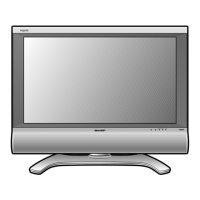
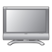
DISASSEMBLY INSTRUCTIONS
B1-1
1. REMOVAL OF MECHANICAL PARTS
AND P.C. BOARDS
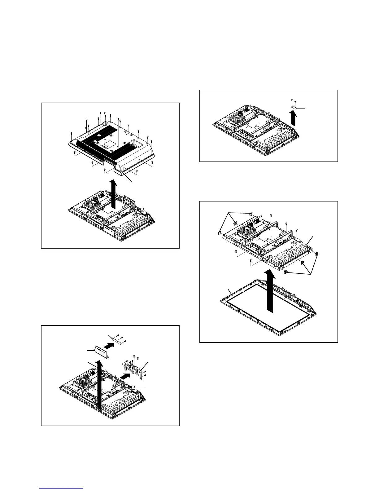
1-2: OPERATION PCB (Refer to Fig. 1-2)
1.
2.
3.
4.
5.
6.
7.
8.
Disconnect the following connector:
(CP2203).
Remove the Speaker Ass'y.
Remove the Plate Button in the direction of arrow (A).
Remove the 3 screws 1.
Remove the Operation PCB in the direction of arrow (B).
Remove the 5 screws 2.
Remove the 2 screws 3.
Remove the Angle Hinge in the direction of arrow (C).
Fig. 1-2
1-1: BACK CABINET (Refer to Fig. 1-1)
1.
2.
3.
Remove the 13 screws 1.
Remove the 7 screws 2.
Remove the Back Cabinet in the direction of arrow.
Fig. 1-1
1-4: LCD BLOCK (Refer to Fig. 1-4)
1.
2.
3.
Remove the Holder Panel.
Remove the 5 screws 1.
Remove the LCD Block in the direction of arrow.
Fig. 1-4
1-3: REMOCON PCB (Refer to Fig. 1-3)
1.
2.
3.
Disconnect the following connector:
(CP2201).
Remove the 2 screws 1.
Remove the Remocon PCB in the direction of arrow.
Fig. 1-3
Operation PCB
1
Plate Button
(B)
(A)
1
1
(C)
2
2
2
2
2
3
3
Back Cabinet
2
1
1
Holder Panel
1
1
1
LCD Block
Holder Panel
Remocon PCB
1
1
Front Cabinet
Angle Hinge
1
1
1
1
1
1
1
1
1
1
1
1
2
2
2
2
2
2
1
Speaker Ass'y
Speaker Ass'y