DISASSEMBLY INSTRUCTIONS
B1-2
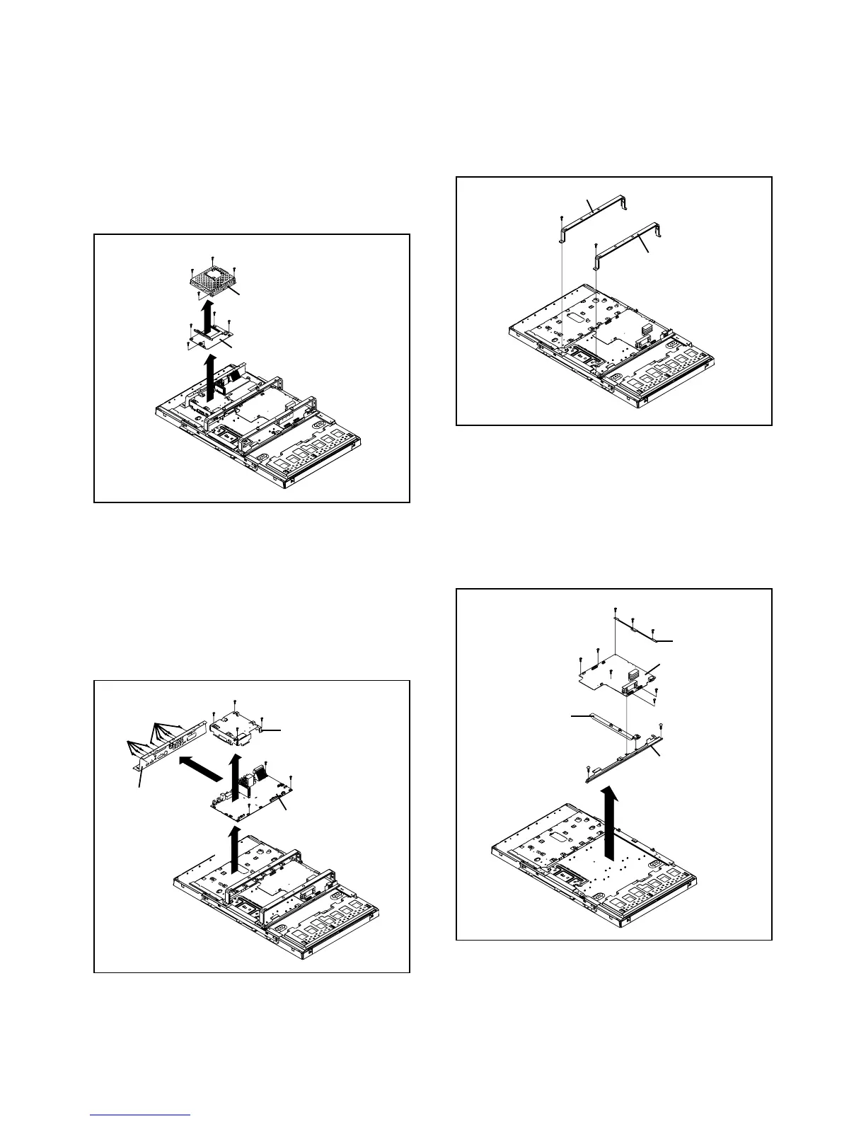
1-7: ANGLE MAIN (Refer to Fig. 1-7)
1.
2.
Remove the 2 screws 1.
Remove the Angle Main.
Fig. 1-7
1-8: POWER PCB (Refer to Fig. 1-8)
1.
2.
3.
4.
5.
6.
Disconnect the following connector:
(CP406).
Remove the 5 screws 1.
Remove the 3 screws 2.
Remove the 2 screws 3.
Remove the Angle PCB-1 and Holder PCB Ass'y.
Remove the POWER PCB and Angle PCB-3 in the
direction of arrow.
1
Angle PCB-1
Fig. 1-8
1
1
1
POWER PCB
Angle Main
1
1
Angle Main
2
2
Holder PCB Ass'y
Angle PCB-3
1
2
3
3
1-5: DIGITAL PCB (Refer to Fig. 1-5)
1.
2.
3.
4.
5.
Disconnect the following connectors:
(CP3801, CP3802).
Remove the 4 screws 1.
Remove the Shield Digital in the direction of arrow (A).
Remove the 4 screws 2.
Remove the Digital PCB in the direction of arrow (B).
Fig. 1-5
Fig. 1-6
1-6: MAIN PCB (Refer to Fig. 1-6)
1.
2.
3.
4.
5.
6.
7.
8.
Disconnect the following connectors:
(CP4307, CP6501, CP6503, CP6504, CP7200).
Remove the 4 screws 1.
Remove the 6 screws 2.
Remove the Plate Jack in the direction of arrow (A).
Remove the 4 screws 3.
Remove the Shield Scaler in the direction of arrow (B).
Remove the 3 screws 4.
Remove the Main PCB in the direction of arrow (C).
(B)
(A)
Shield Digital
1
1
1
1
2
2
2
2
Digital PCB
1
2
Main PCB
Plate Jack
Shield Scaler
3
4
(B)
(A)
3
3
3
4
4
(C)