EasyManua.ls Logo

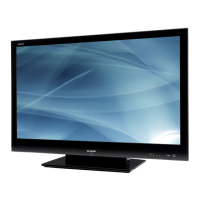
Sharp LC-32LE700E User Manual

Sharp LC-32LE700E
164 pages
To Next Page IconTo Next Page
Page #1 background imageLoading...
Page #1 background image
SERVICE MANUAL
Parts marked with " " are important for maintaining the safety of the set. Be sure to replace these parts with specified ones for maintaining the
safety and performance of the set.
This document has been published to be used for
after sales service only.
The contents are subject to change without notice.
SAFETY PRECAUTION
IMPORTANT SERVICE SAFETY PRE-
CAUTION............................................................i
Precautions for using lead-free solder ...............ii
End of life disposal............................................iii
CHAPTER 1. SPECIFICATIONS
[1] SPECIFICATIONS ......................................... 1-1
CHAPTER 2. OPERATION MANUAL
[1] OPERATION MANUAL .................................. 2-1
CHAPTER 3. DIMENSIONS
[1] DIMENSIONS ................................................ 3-1
CHAPTER 4. REMOVING OF MAJOR PARTS
[1] REMOVING OF MAJOR PARTS ................... 4-1
CHAPTER 5. ADJUSTMENT
[1] ADJUSTMENT PROCEDURE....................... 5-1
CHAPTER 6. TROUBLESHOOTING TABLE
[1] TROUBLESHOOTING TABLE....................... 6-1
[2] LED flashing specification at the time of the
error.............................................................. 6-19
CHAPTER 7. MAJOR IC INFORMATIONS
[1] MAJOR IC INFORMATIONS.......................... 7-1
CHAPTER 8. OVERALL WIRING/SYSTEM BLOCK
DIAGRAM
[1] OVERALL WIRING DIAGRAM (LC-32LE/
LU/LX700) .....................................................8-1
[2] OVERALL WIRING DIAGRAM (LC-40LE/
LU/LX700) .....................................................8-2
[3] OVERALL WIRING DIAGRAM (LC-46LE/
LU/LX700) .....................................................8-3
[4] OVERALL WIRING DIAGRAM (LC-
52LE700).......................................................8-4
[5] SYSTEM BLOCK DIAGRAM (LC-32LE/LU/
LX700)...........................................................8-5
[6] SYSTEM BLOCK DIAGRAM (LC-40LE/LU/
LX700)...........................................................8-6
[7] SYSTEM BLOCK DIAGRAM (LC-46LE/LU/
LX700, LC-52LE700).....................................8-7
CHAPTER 9. PRINTED WIRING BOARD ASSEM-
BLIES
[1] KEY Unit, R/C, LED Unit, ICON Unit .............9-1
[2] MAIN Unit ......................................................9-2
CHAPTER 10. SCHEMATIC DIAGRAM
[1] DESCRIPTION OF SCHEMATIC DIA-
GRAM..........................................................10-1
[2] SCHEMATIC DIAGRAM..............................10-2
Parts Guide
TopPage
CONTENTS
LC-32/40/46LE700E/RU/S,LU700E/S,LX700E/RU,LC-52LE700E/RU/S
No. S89B4LC32L700
MODELS
LC-32LE700E/RU/S, LC-32LU700E/S
LC-32LX700E/RU
LC-40LE700E/RU/S, LC-40LU700E/S
LC-40LX700E/RU
LC-46LE700E/RU/S, LC-46LU700E/S
LC-46LX700E/RU
LC-52LE700E/RU/S
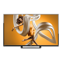
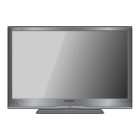
LCD COLOUR TELEVISION
In the interests of user safety (required by safety regulations in some countries) the set should be restored to its
original condition and only parts identical to those specified should be used.
Question and Answer IconNeed help?

Do you have a question about the Sharp LC-32LE700E and is the answer not in the manual?

Sharp LC-32LE700E Specifications

General IconGeneral
Display diagonal32 \
Native aspect ratio16:9
Native refresh rate100 Hz
RMS rated power20 W
Number of speakers2
PC in (D-Sub)Yes
HDMI ports quantity4
USB 2.0 ports quantity1
Weight and Dimensions IconWeight and Dimensions
Depth (without stand)92 mm
Width (without stand)767 mm
Height (without stand)502 mm
Weight (without stand)13500 g

Summary

Safety and Precautions

Important Service Safety Precautions

Covers critical service safety guidelines for user protection.

Lead-Free Solder Precautions

Detailed guidance on using lead-free solder for repairs.

End of Life Disposal

Guidelines for proper disposal of used electrical and electronic products.

Chapter 1. Specifications

Specifications Details

Technical specifications for various TV models.

Chapter 2. Operation Manual

Operation Manual Overview

Instructions for operating the TV set.

Chapter 3. Dimensions

Unit Dimensions

Physical dimensions of the TV units.

Chapter 4. Removing Major Parts

Major Parts Removal Procedure

Step-by-step guide for removing key components.

Chapter 5. Adjustment Procedures

Adjustment Procedure Overview

Steps for adjusting settings after part replacement.

Chapter 6. Troubleshooting Table

Troubleshooting Guide

Diagnostic flowcharts for identifying and resolving common issues.

Chapter 7. Major IC Informations

Major IC Descriptions

Details and functions of key integrated circuits.

Chapter 8. Wiring and Block Diagrams

Overall Wiring Diagrams

System wiring diagrams for different model series.

Chapter 9. Printed Wiring Board Assemblies

PWB Layouts

Visual representation of component placement on PWBs.

Chapter 10. Schematic Diagrams

Schematic Diagram Description

Explanations of schematic conventions and symbols.

Cabinet and Mechanical Parts Lists

LC-32/40/46LE700 Series Parts

Lists mechanical components for 32/40/46 inch models.

LC-40LE/LU/LX700 Series Parts

Lists mechanical components for 40 inch models.

LC-46LE/LU/LX700 Series Parts

Lists mechanical components for 46 inch models.

LC-52LE700 Series Parts

Lists mechanical components for 52 inch models.

LCD Panel Module Unit Parts Lists

LC-32/40/46LE700 Series Parts

LCD panel module parts for 32/40/46 inch models.

LC-40LE/LU/LX700 Series Parts

LCD panel module parts for 40 inch models.

LC-46LE/LU/LX700 Series Parts

LCD panel module parts for 46 inch models.

LC-52LE700 Series Parts

LCD panel module parts for 52 inch models.

Supplied Accessories and Packing

Accessory List

List of items included with the product.

Packing Parts List

List of non-replacement packing materials.

Service Jigs

Service Jigs List

Tools used specifically for servicing.

Related product manuals