MX-3610N ADJUSTMENTS AND SETTINGS 4 – 86
SIM50-6
* Item A, B: When the adjustment value is increased, the scan
timing is delayed.
* Item C - H: When the adjustment value is increased, the
image loss is increased.
* Item A - H: 1 step = 0.1mm change
* The SPF rear edge image loss setting is provided for
countermeasures against the case when shades are
produced.
5) Select an adjustment mode with the scroll key.
(SIM50-12)
(SIM50-6)
6) Enter an adjustment value with 10-key, and press [OK] key.
(Change for change in the adjustment value: 0.1mm/step)
(When the adjustment value is increased, the print image is
shifted to the rear.)
Repeat the procedures of 2) - 6) until a satisfactory result is
obtained.
ADJ 18 Copy image position and image
loss adjustment
(Manual adjustment)
Normally if the adjustment is executed by ADJ 4 (automatic adjust-
ment), there is no need to execute this adjustment.
Only when the manual adjustment is required, execute this adjust-
ment.
In other words, this manual adjustment is executed when a satis-
factory result is not obtained from the automatic adjustment (ADJ
4).
18-A Copy image position, image loss, and void
area adjustment (Manual adjustment)
(Document table mode)
This adjustment must be performed in the following cases:
* When the scanner (reading) section is disassembled.
* When the scanner (reading) unit is replaced.
* When the LSU is replaced or removed.
* When the registration roller section is disassembled.
* U2 trouble has occurred.
* The PCU PWB has been replaced.
* The EEPROM of the PCU PWB has been replaced.
* The scanner control PWB has been replaced.
* The EEPROM on the scanner control PWB has been replaced.
Before executing this adjustment, be sure to confirm that the ADJ
4/ADJ 5 Print engine image skew, image position, image magnifica-
tion ratio, void area adjustments has been completed normally.
1) Place a scale on the document table as shown in the figure
below.
Place a scale so that it is in parallel with the scanning direction
and that its lead edge is in contact with the document guide
plate.
Place white paper on the document table so that the scale lead
edge can be seen.
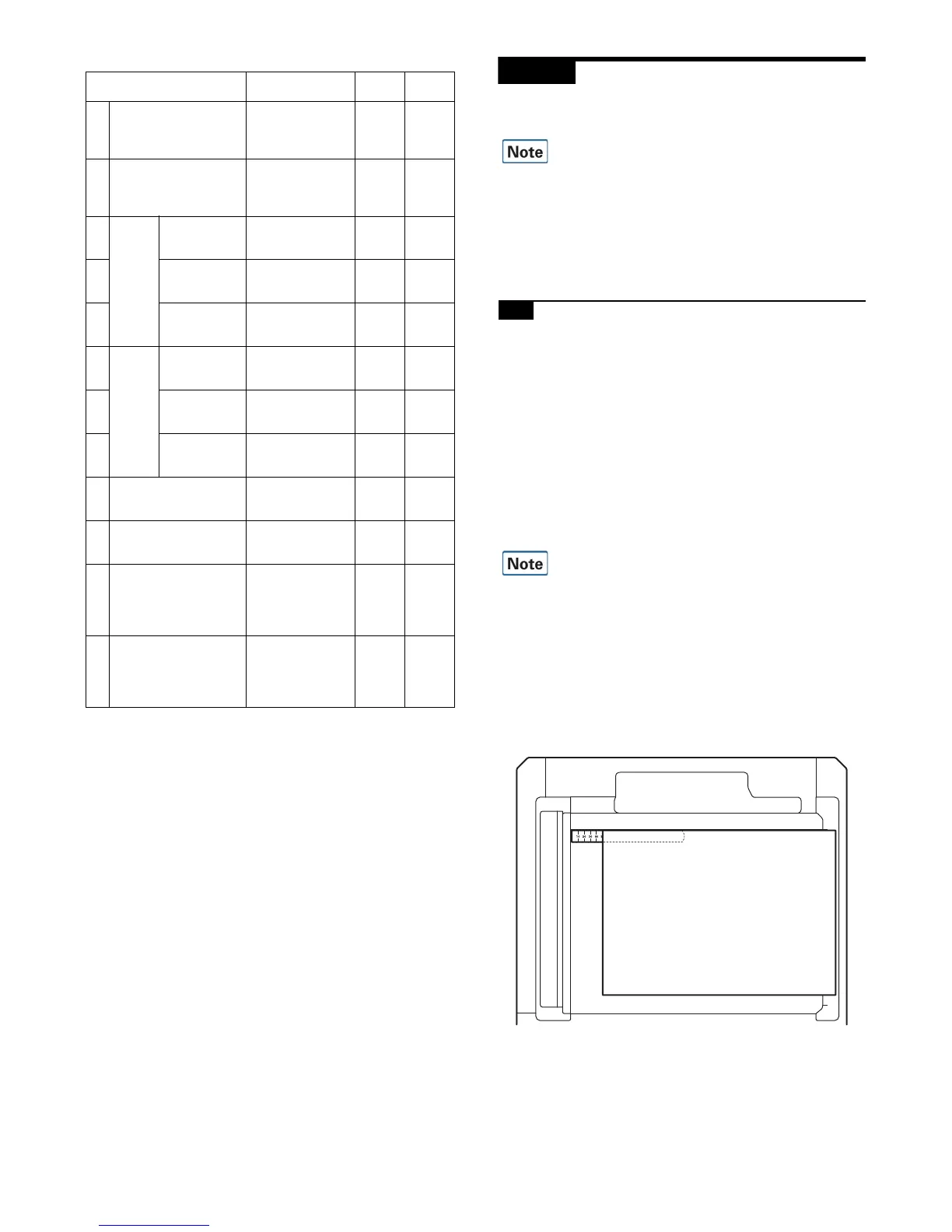
Item/Display Content
Setting
range
Default
value
A SIDE1 Front surface
document scan
position adjustment
(CCD)
1 - 99 50
B SIDE2 Back surface
document scan
position adjustment
(CCD)
1 - 99 50
C Image
loss
amount
setting
SIDE1
LEAD_EDGE
(SIDE1)
Front surface lead
edge image loss
amount setting
0 - 99 20
D FRONT_REAR
(SIDE1)
Front surface side
image loss amount
setting
0 - 99 20
E TRAIL_EDGE
(SIDE1)
Front surface rear
edge image loss
amount setting
0 - 99 40
F Image
loss
amount
setting
SIDE2
LEAD_EDGE
(SIDE2)
Back surface lead
edge image loss
amount setting
0 - 99 20
G FRONT_REAR
(SIDE2)
Back surface side
image loss amount
setting
0 - 99 20
H TRAIL_EDGE
(SIDE2)
Back surface rear
edge image loss
amount setting
0 - 99 40
I OFFSET_SPF1 RSPF front surface
document off-center
adjustment
1 - 99 50
J OFFSET_SPF2 RSPF back surface
document off-center
adjustment
1 - 99 50
K SCAN_SPEED_SPF1 RSPF document
front surface
magnification ratio
adjustment (Sub
scan)
1 - 99 50
L SCAN_SPEED_SPF2 RSPF document
back surface
magnification ratio
adjustment (Sub
scan)
1 - 99 50
SPF(SIDE1) Front surface mode
SPF(SIDE2) Back surface mode
OFFSET SPF1 Front surface mode
OFFSET SPF2 Back surface mode