MX-5001N SIMULATION 6 – 97
A. (RRC-A) Timing from starting document scanning to specifying
the image lead edge reference is adjusted. (01.mm/step)
* When the value is decreased, the timing is advanced. When
the value is increased, the timing is delayed.
B - F. (RRC-B) Timing of paper (resist roller ON) for the image posi-
tion on the transfer belt is adjusted. (0.1mm/step)
* When the value is decreased, the timing is delayed. When the
value is increased, the timing is advanced.
G. (LEAD) The lead edge image loss amount is adjusted. (0.1mm/
step)
* When the value is increased, the image loss is increased.
H. (SIDE) The side image loss amount is adjusted.
* When the value is increased, the image loss is increased.
(0.1mm/step)
I. (DEN-A) The paper lead edge void amount is adjusted. (0.1mm/
step)
* When the value is increased, the void is increased.
J. (DEN-B) The paper rear edge void amount is adjusted. (0.1mm/
step)
* When the value is increased, the void is increased.
K. (FRONT/REAR) The void amount on the right and left edges of
paper is adjusted. (0.1mm/step)
50-2
Purpose
Adjustment
Function (Purpose)
Used to adjust the copy image position and
the image loss. (This simulation is a simpli-
fied version of SIM 50-1).
Section
Operation/Procedure
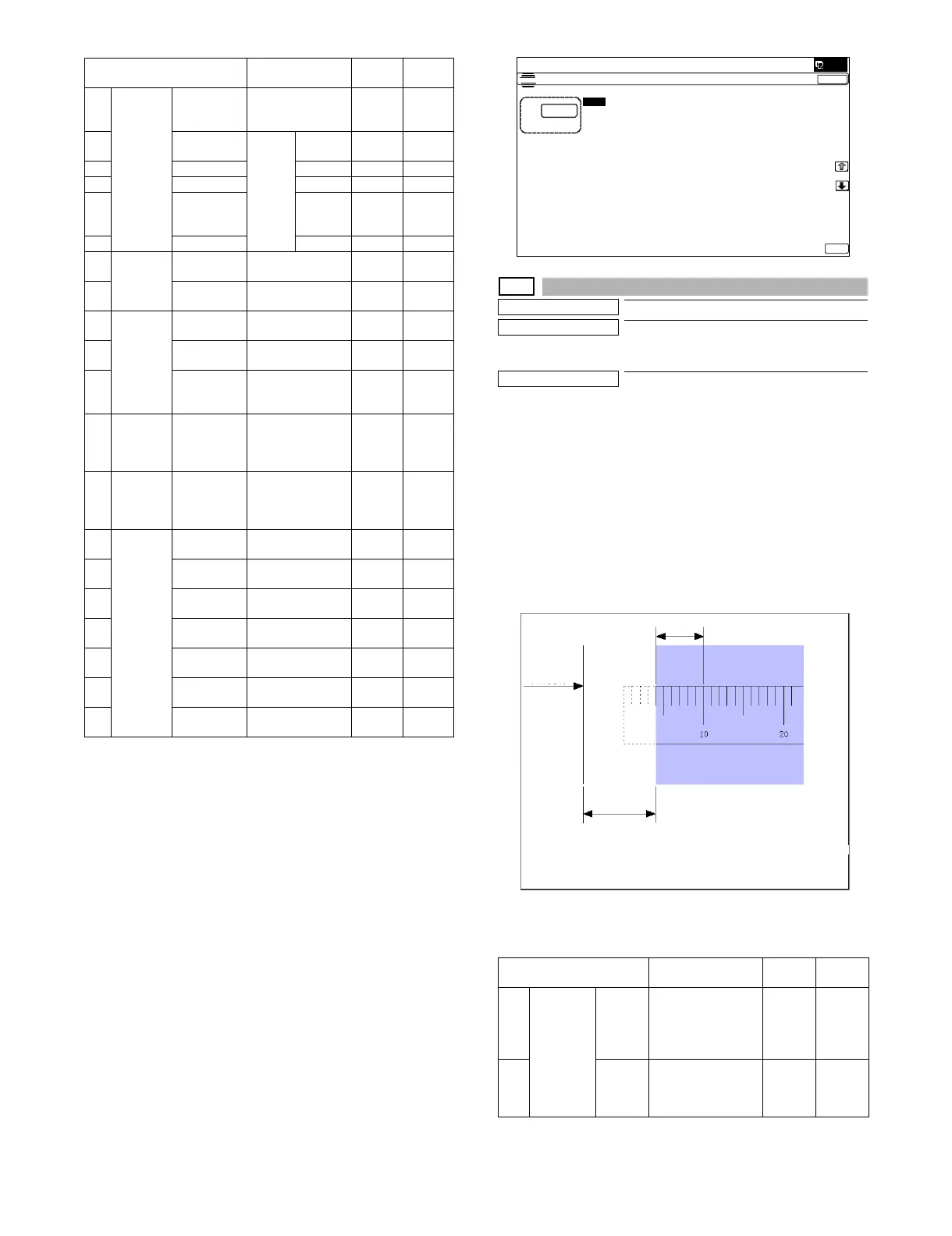
1) Set item A (L1) and item B (L2) to 0.
2) Place a rule on the left edge of the document table, and make
a copy at a magnification ratio of 400%.
3) Measure the length of L1 and L2 on the copied image in the
unit of 0.1mm (referring to the figure below). Enter the adjust-
ment values of L1 x 10 and L2 x 10. Be sure to enter the both
adjustment values of L1 and L2.
L1: Distance from the lead edge of the copied image to 10mm
scale.
L2: Distance from the paper lead edge to the copy image lead
edge.
4) Press [EXECUTE] key. (The set value is saved.)
5) Make a copy at the magnification ratio of 100%, and adjust the
rear edge void.
Item/Display Content
Setting
range
Default
value
A Lead
edge
adjust-
ment
value
RRCA Document lead
edge reference
position (OC)
0 - 99 50
B RRCB-CS12 Resist
motor
ON
timing
adjust-
ment
Standard
Tray
1 - 99 50
C RRCB-CS34 Desk 1 - 99 50
D RRCB-LCC LCC 1 - 99 50
E RRCB-MFT Manual
paper
feed
1 - 99 50
F RRCB-ADU ADU 1 - 99 50
GImage
loss area
setting
value
LEAD Lead edge image
loss area setting
0 - 99 30
H SIDE Side image loss
area adjustment
0 - 99 20
I Void area
adjust-
ment
DENA Lead edge void
area adjustment
1 - 99 30
J DENB Rear edge void
area adjustment
1 - 99 30
K FRONT/
REAR
FRONT/REAR
void area
adjustment
1 - 99 20
LOff-
center
adjust-
ment
OFSET_OC OC document off-
center adjustment
1 - 99 50
M Magnifica
tion ratio
correc-
tion
SCAN
_SPEED
_OC
SCAN sub
scanning
magnification ratio
adjustment (CCD)
1 - 99 50
N Sub
scanning
direction
print area
correction
value
DENB-MFT Manual feed
correction value
1 - 99 50
O DENB-CS1 Tray 1 correction
value
1 - 99 50
P DENB-CS2 Tray 2 correction
value
1 - 99 50
Q DENB-CS3 Tray 3 correction
value
1 - 99 50
R DENB-CS4 Tray 4 correction
value
1 - 99 50
S DENB-LCC LCC correction
value
1 - 99 50
T DENB-ADU ADU correction
value
1 - 99 50
Item/Display Description
Setting
range
Default
value
AActual
measurem
ent value
L1 Distance from the
image lead edge to
the scale of 10mm.
(Platen 400%,
0.1mm increment)
0 - 999 -
B L2 Distance from the
paper lead edge to
the image lead edge
(0.1mm increment)
0 - 999 0
ǂǂǂ6,08/$7,21
ǂǂ12
&/26(
7(67
/($'('*($'-8670(179$/8(
$˖
˷
˹
˖55&$
$˖
˖55&%
&6
%˖
˖55&%
&6
&˖
˖55&%
/&&
'˖
˖55&%
$'8
)˖
˖55&%
0)7
(˖
˖/($'
*˖
˖6,'(
+˖
˖'(1$,˖
˖'(1%
-˖
˖)5217
5($5
.˖
˖2)6(7
B2&
/˖
2.
Paper lead
edge
L1
L2
400% enlargement copy
Fig. 1
 Loading...