MX-M182 ADJUSTMENT 6-2
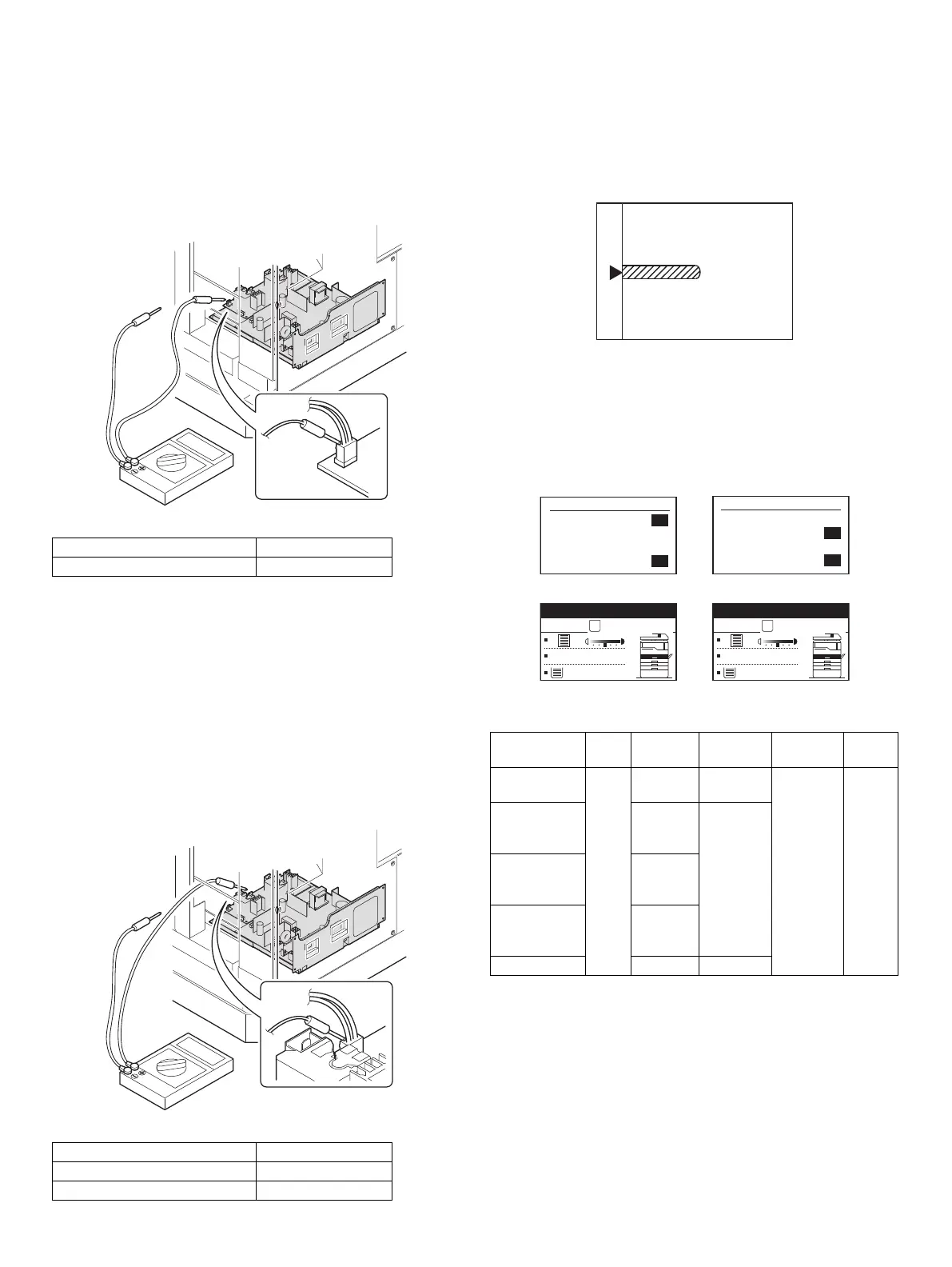
(3) Developing bias voltage check
Note:Use a digital multi-meter with an internal resistance of 10M or
more.
1) Set the digital multi-meter range above 500 Vdc.
2) Put the test rod of the digital multi-meter on the developing bias
voltage output check pin.
3) Turn on the power, execute SIM25-1.
<Specification>
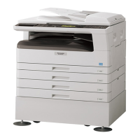
(4) Grid bias voltage check
Note:Use a digital multi-meter with an internal resistance of 10M or
more.
1) Set the digital multi-meter range above 600 Vdc.
2) Put the test rod of the digital multi-meter on the grid bias voltage
output check pin.
3) Turn on the power.
(The voltage is outputted in the grid bias High output mode during
warming up, and in the grid bias Low output mode when warming up
is completed.)
<Specification>
B. Mechanism section
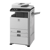
(1) Image position adjustment
a. OC image lead edge position adjustment (SIM 50-1)
Note:In advance to this adjustment, the sub scanning magnification ratio
adjustment must be performed.
1) Set a scale on the OC table as shown below.
2) Make a copy.
3) Check the copy output. If necessary, perform the following
adjustment procedures.
4) Execute SIM 50-01.
Select a desired mode with the arrow keys, enter the adjustment
value with 10-key, and press [OK] key.
When [START] key is pressed, a sheet is printed.
<Adjustment specification>
5) Set the OC lead edge position set value (RRC-A) to [1]
The OC image scanning start position is shifted inside the document
edge.
6) Set the main cassette lead edge void adjustment value (DEN-A)* to [1]
The lead edge void becomes the minimum.
Mode Specification
Developing bias voltage DC - 400±10V
Mode Specification
Grid bias LOW DC - 380±8V
Grid bias HIGH DC - 525±10V
Adjustment
mode
SIM Display
text array
Set
value
Spec
value
Set
range
OC image lead
edge position
SIM
50-1
RRC-A R/0.1 Lead edge
void:
1 - 4mm
Image loss:
3mm or
less
1 - 99
Main cassette
print start
position
TRAY1 H/0.1
2nd cassette
print start
position
TRAY2
Multi bypass
tray print start
position
MFT
Lead edge void DEN-A B/0.05
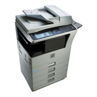
(Mode selection window 1)
Sim50-1 LEAD EDGE
1:TRAY1
2:TRAY2
3:MFT
1/2 [ 1- 99]
50
50
50
50
(Mode selection window 2)
Sim50-1 LEAD EDGE
4:DEN-A
5:RRC-A
6:DEN-B
2/2 [ 1- 99]
50
1
50
50
Ready to copy.
S
100%
A4
(Copy start window)
Copies in progress.
S
100%
A4
(Copy execution window)