MX-M182 ADJUSTMENT 6-3
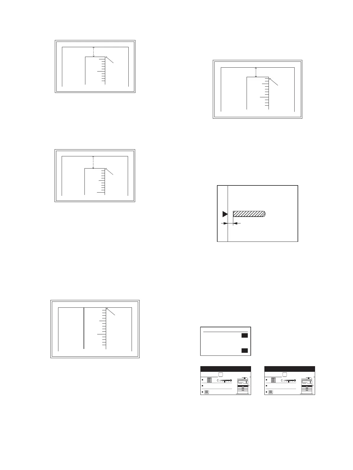
7) Set the main cassette print start position value (TRAY1) to [1] and
make a copy.
The print start position is shifted inside the document edge.
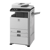
8) Measure the image loss R of the copied image. Enter the set value of
the image scanning lead edge position (RRC-A) again.
• 1 step of the set value corresponds to about 0.1mm shift.
• Calculate the set value from the formula below.
R/0.1(mm) = Image loss set value
<R: Image loss measurement value (mm)>
Example: 4/0.1 = 40 = about 40
Note:If the set value is not obtained from the above formula, perform the
fine adjustment.
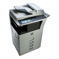
9) Measure the distance H between the paper lead edge and the image
print start position. Set the image print start position set value
(TRAY1) again.
• 1 step of the set value corresponds to about 0.1mm shift.
• Calculate the set value from the formula below.
H/0.1(mm) = Image print start position set value
<H: Print start position measurement value (mm)>
Example: 5/0.1 = 50 = about 50
Note:If the set value is not obtained from the above formula, perform the
fine adjustment.
10) Set the lead edge void adjustment value (DEN-A)* again.
• 1 step of the set value corresponds to about 0.1mm shift.
• Calculate the set value from the formula below.
B/0.05 (mm) = Lead edge void adjustment value
<B: Lead edge void (mm)>
Example: When setting the lead edge void to 2.5mm
:2.5 /0.05 = about 50
Note:If the set value is not obtained from the above formula, perform the
fine adjustment.
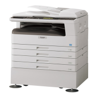
b. SPF image lead edge position adjustment (SIM50-6)
1) Set a scale on the OC table as shown below.
Note:Since the printed copy is used as a test chart, put the scale in
parallel with the edge lines.
2) Make a copy, Then use the copy output as an original to make an
SPF copy again.
3) Check the copy output. If necessary, perform the following
adjustment procedures.
4) Execute SIM 50-6.
5) Set the SPF lead edge position set value (SIDE1) so that the same
image is obtained as that obtained in the previous OC image lead
edge position adjustment.
5
10
5mm
4mm
*The dimension varies depending on the model.
10
5mm
0mm
5
* The scanning edge is set.
(A line may be printed by scanning the document edge.)
5
10
0mm
0mm
*Fit the print edge with the paper edge, and perform the
lead edge adjustment.
(Mode selection window)
Ready to copy.
S
100%
A4
(Copy start window)
Copies in progress.
S
100%
A4
(Copy execution window)
Sim50-6 SPF EDGE
1:SIDE1
2:SIDE2
3:END EDGE
[ 1- 99]
50
50
50
50