8
9
6
5
21
4
3
7
5
10
15
1
11
6
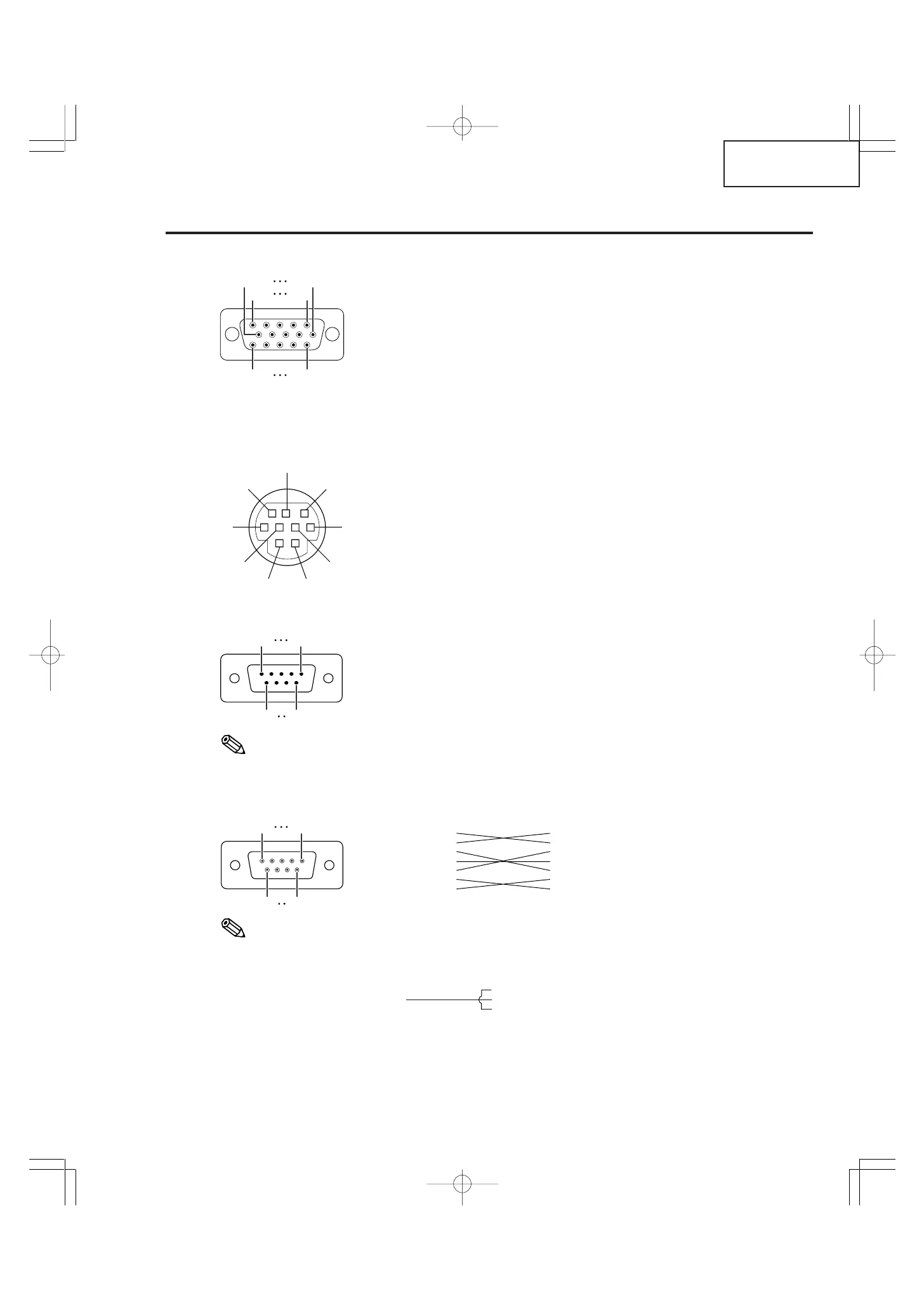
RS-232C Terminal: 9-pin Mini DIN female connector
Pin No. Signal Name I/O Reference
1 Not connected
2 RD Receive Data Input Connected to internal circuit
3 SD Send Data Output Connected to internal circuit
4 Not connected
5 SG Signal Ground Connected to internal circuit
6 Not connected
7 RS Connected to Pin 8
8 CS Connected to Pin 7
9 Not connected
DIN-D-sub RS-232C adaptor: 9-pin D-sub male connector
Pin No. Signal Name I/O Reference
1 Not connected
2 RD Receive Data Input Connected to internal circuit
3 SD Send Data Output Connected to internal circuit
4 Not connected
5 SG Signal Ground Connected to internal circuit
6 Not connected
7 RS Connected to internal circuit
8 CS Connected to internal circuit
9 Not connected
Note
• Pin 8 (CS) and Pin 7 (RS) are short circuited inside the projector.
RS-232C Cable recommended connection: 9-pin D-sub female connector
Pin No. Signal Pin No. Signal
1CD 1 CD
2RD 2 RD
3SD 3 SD
4ER 4 ER
5SG 5 SG
6DR 6 DR
7RS 7 RS
8CS 8 CS
9CI 9 CI
Note
• Depending on the controlling device used, it may be necessary to connect Pin 4 and Pin 6 on the controlling
device (e.g. PC).
INPUT 1 and OUTPUT RGB Signal Terminal: 15-pin Mini D-sub female connector
RGB Input
1. Video input (red)
2. Video input (green/sync on green)
3. Video input (blue)
4. Not connected
5. Not connected
6. Earth (red)
7. Earth (green/sync on green)
8. Earth (blue)
9. Not connected
10. GND
11. Not connected
12. Bi-directional data
13. Horizontal sync signal: TTL level
14. Vertical sync signal: TTL level
15. Data clock
Component Input
1. P
R
(C
R
)
2. Y
3. P
B
(C
B
)
4. Not connected
5. Not connected
6. Earth (P
R
)
7. Earth (Y)
8. Earth (P
B
)
9. Not connected
10. Not connected
11. Not connected
12. Not connected
13. Not connected
14. Not connected
15. Not connected
Projector
Pin No.
4
5
6
PC
Pin No.
4
5
6
15
69
51
96