R-775(W)R-785(AL) - 13
Fuse F2 F8A blows when the door is opened.
Home fuse blows when power cord is plugged into wall outlet.
Fuse F1 20A blows when power cord is plugged into wall outlet.
Nothing appears in display when power cord is plugged into wall outlet
and the door is opened and closed.
Display does not operate properly when STOP button is pressed.
Oven lamp does not light when door is opened. (Display operates.)
Oven does not start when the START button is pressed. (Display operates.)
Oven lamp does not light and turntable motor does not operate.
Fan motor does not operate. (Oven lamp lights.)
Turntable motor does not operate. (Oven lamp lights.)
Oven or any electrical parts (except fan motor) does not stop when
cooking time is 0 or STOP button is pressed.
Display operates properly but all electrical parts do not operate.
Oven goes into cook cycle but shuts down before end of cooking cycle.
Oven seems to be operating but little or no heat is produced in oven
load. (Microwave power control is set at HIGH)
Oven does not seem to be operating properly during variable cooking
condition except HIGH cooking condition.
Oven goes into cook cycle but shuts down before end of cooking cycle.
Grill heating element does operate.
Oven seems to be operating but little or no heat is produced in oven
load. (Microwave power does not seem to be generated properly)
Top or Bottom Grill heating element does not heat.
OFF
CONDITION
COOKING
CONDITION
(COMMON MODE)
MICROWAVE
COOKING
CONDITION
GRILL COOKING
CONDITION
DUAL COOKING
CONDITION
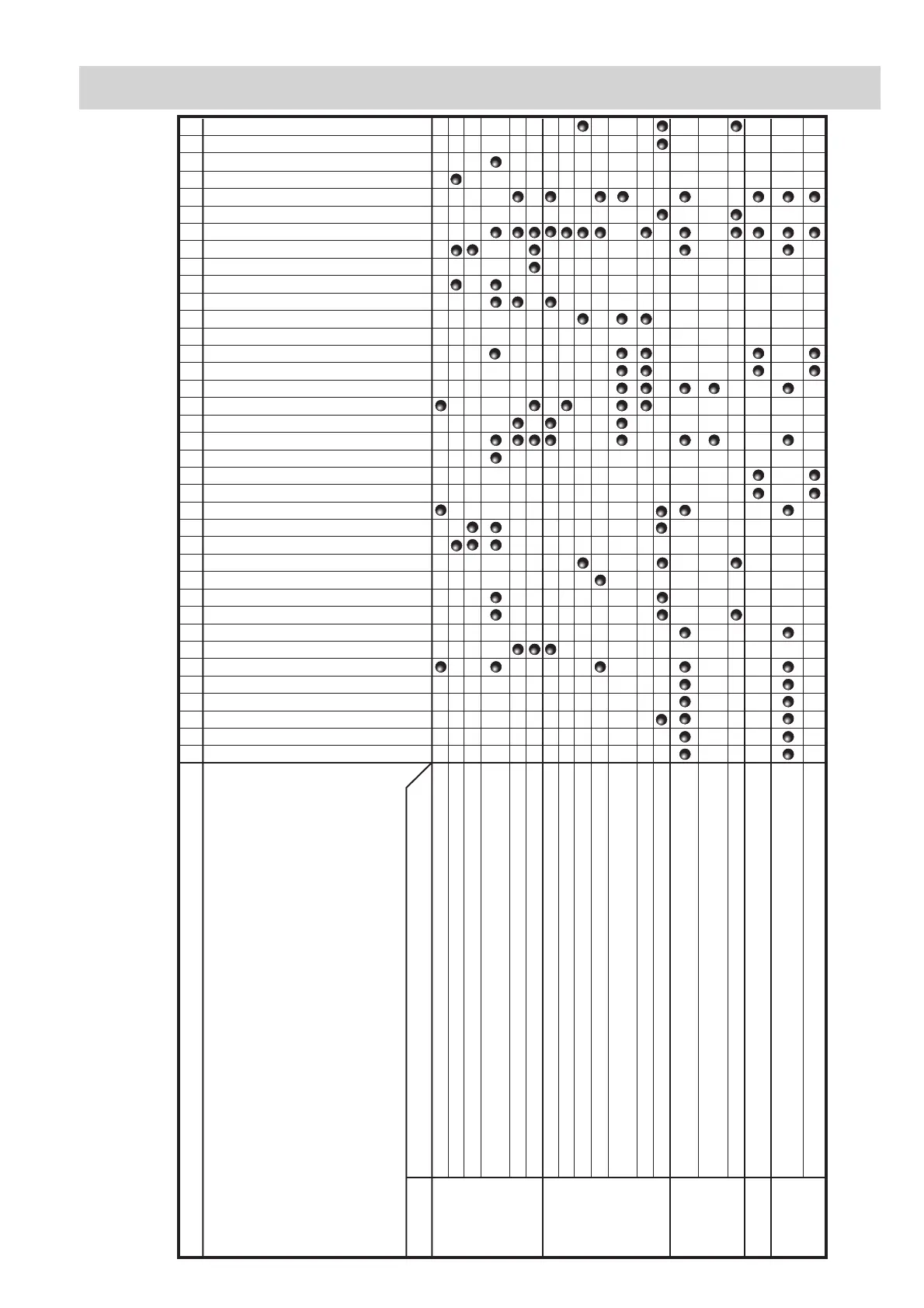
CONDITION PROBLEM
BLOCKED COOLING FAN
BLOCKED CONVECTION FAN
NO POWER AT WALL OUTLET
HOME FUSE OR BREAKER
MIS-ADJUSTMENT OF SWITCHES
BLOCKED VENTILATION OPENINGS
OPENED WIRE HARNESS
SHORTED WIRE HARNESS
OVEN LAMP
POWER SUPPLY CORD
FOIL PATTERN ON P.W.B.
RELAY RY6
RELAY RY4
RELAY RY5
RELAY RY3
RELAY RY2
RELAY RY1
KEY/ JOG UNIT
CONTROL UNIT
TC TRANSFORMER
BOTTOM GRILL HEATING ELEMENT
TOP GRILL HEATING ELEMENT
FUSE F8A F2
FUSE 20A F1
NOISE FILTER
FAN MOTOR
TURNTABLE MOTOR
THERMAL CUT-OUT 145˚C TC2
THERMAL CUT-OUT 125˚C TC1
MONITOR SWITCH SW3
STOP SWITCH SW2
MONITORED LATCH SWITCH SW1
HIGH VOLTAGE CAPACITOR
H.V. HARNESS
H.V. RECTIFIER ASSEMBLY
HIGH VOLTAGE TRANSFORMER
MAGNETRON
ABC DEEEFFGGH I JKK LM NNNNNNO
TEST PROCEDURE
POSSIBLE CAUSE
AND
DEFECTIVE PARTS
TROUBLESHOOTING GUIDE