R-775(W)R-785(AL) - 21
The touch control section consists of the following units as
shown in the touch control panel circuit.
(1) Jog Switch Unit
(2) Control Unit (The Control unit consists of Power unit
and CPU unit.)
The principal functions of these units and signals commu-
nicated among them are explained below.
Jog Switch Unit
The jog switch unit is composed of a matrix, signals
generated in the LSI are sent to the jog switch unit from
P40, P41, P76 and P77.
When a button is touched, a signal is completed through
the jog switch unit and passed back to the LSI through P50
- P53 to perform the function that was requested.
Control Unit
Control unit consists of LSI, power source circuit, synchro-
nizing signal circuit, reset circuit, buzzer circuit, indicator
circuit, encoder circuit,potentiometer circuit and back light
circuit.
1) LSI
This LSI controls the tact switch strobe signal, relay
driving signal for oven function and indicator signal.
2) Power Source Circuit
This circuit generates voltage necessary in the control
unit.
Symbol Voltage Application
VC -5.2V LSI(IC1)
3) Synchronizing Signal Circuit
The power source synchronizing signal is available in
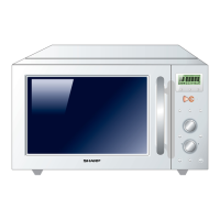
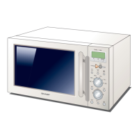
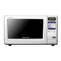
TOUCH CONTROL PANEL ASSEMBLY
OUTLINE OF TOUCH CONTROL PANEL
order to compose a basic standard time in the clock
circuit. It accompanies a very small error because it
works on commercial frequency.
4) Reset Circuit
A circuit to generate a signals which resets the LSI to
the initial state when power is supplied.
5) Buzzer Circuit
The buzzer is responsive to signals from the LSI to emit
audible sounds (tact switch touch sound and comple-
tion sound).
6) Stop Switch
A switch to “tell” the LSI if the door is open or closed.
7) Relay Circuit
To drive the magnetron, top and bottom heating ele-
ment, fan motor, turntable motor, touch control trans-
former and light the oven lamp.
8) Encoder
The encoder converts the signal generated by LSI into
the pulse signal, and the pulse signal is returned to the
LSI.
9) Potentiometer Circuit
The circuit makes setting of the cooking mode by
variable resistance.
10) Back Light Circuit
A circuit to drive the back light (Light emitting diodes
LD1 - LD10).
11) Indicator Circuit
This circuit consists 7-digits, 39-segments and 3-com-
mon electrodes using a Liquid Crystal Display.