R-775(W)R-785(AL) - 28
REMOVAL
1. CARRY OUT 3D CHECKS.
2. Remove the one
(1) screw
holding the noise filter to the
chassis support.
3. Release the noise filter from the tabs of the fan duct.
4. Remove the one
(1) screw
holding the chassis support
to the oven cavity front flange.
5. Remove one(1) screw holding the chassis support to the
magnetron.
6. Remove the chassis support from the oven cavity.
7. Disconnect the wire leads from the fan duct.
8. Remove the
one
(1) screw holding the capacitor holder
to the oven cavity back plate.
9. Release the tabs of the capacitor holder from the fan
duct.
10.Remove the
one
(1) screw holding the fan duct to the
oven cavity back plate.
11.Remove the fan duct from the oven.
12.Remove the fan duct from the fan motor shaft accord-
ing to the following procedure.
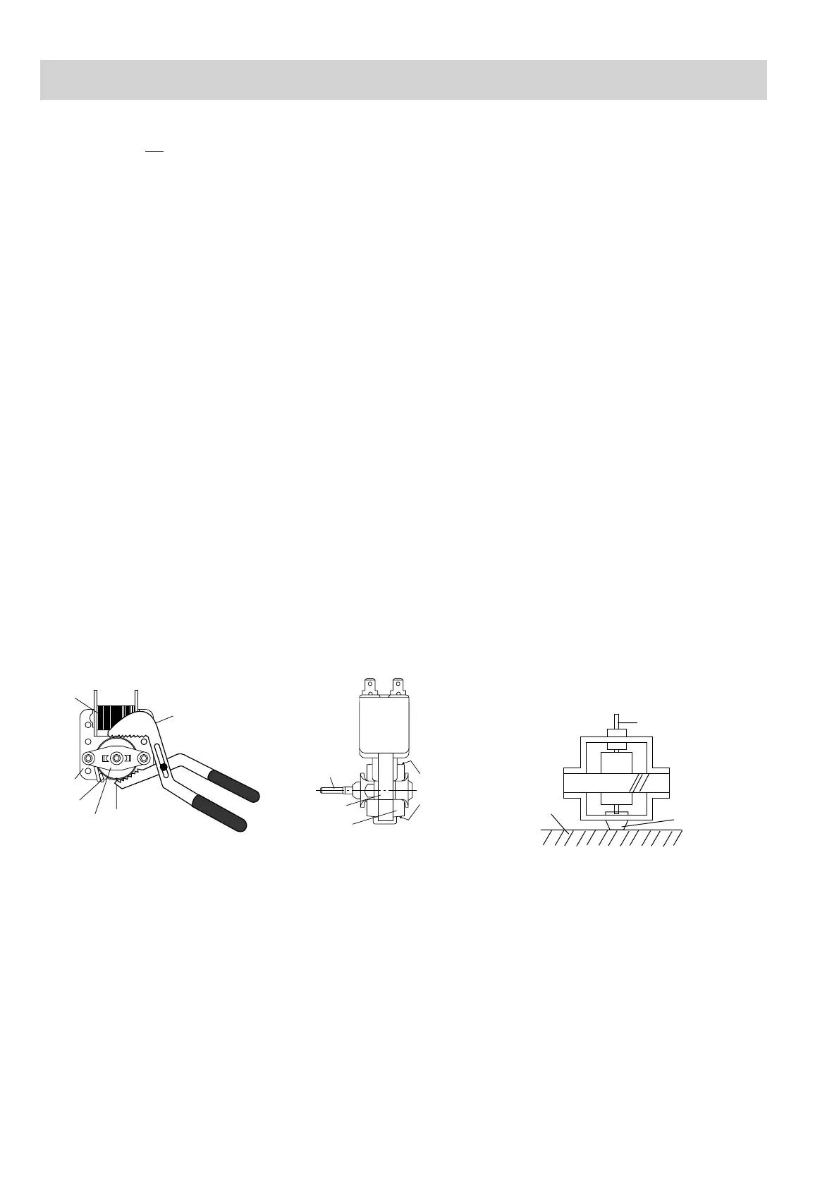
1) Hold the edge of the rotor of the fan motor by using
a pair of groove joint pliers.
CAUTION:
• Make sure that no swarf from the rotor enters
the gap between the rotor & startor of the fan
motor.
• Avoid touch the coil of the fan motor with the
pliers as the coil may become cut or damaged.
• Avoid deforming the bracket whilst using the
pliers.
2) Remove the fan blade assembly from the shaft of
the fan motor by pulling and rotating the fan blade
with your hand.
3) Now, the fan blade is free.
CAUTION:
• Do not reuse the removed fan blade as the
fixing hole may be oversize.
12.Remove the two
(2) screws holding the fan motor to the
fan duct.
13.Now, the fan motor is free.
INSTALLATION
1. Install the the fan motor to the fan duct with the two
(2)
screws.
2. Install the fan blade to the fan motor shaft according to
the following procedure.
1) Hold the centre of the bracket which supports the
shaft of the fan motor on a flat table.
2) Apply the screw lock tight into the hole (for shaft) of
the fan blade.
3) Install the fan blade to the shaft of fan motor by
pushing the fan blade with a small, light weight, ball
peen hammer or rubber mallet.
CAUTION:
• Do not hit the fan blade when installing be-
cause the bracket may be deformed.
• Make sure that the fan blade rotates smoothly
after installation.
• Make sure that the axis of the shaft is not
slanted.
3. Insert the
tabs of
the capacitor holder to the fan duct.
4. Install the fan duct to the oven cavity back plate with the
one (1) screw.
5. Install the capacitor holder to the oven cavity back plate
with the one (1) screw.
6. Re-install the chassis support to the oven cavity
with the
one (1) screw
.
7. Re-fit the one(1) screw to secure the chassis support to
the magnetron.
8. Install the noise filter to the fan duct and
the chassis
support
with the one (1) screw.
9. Re-connect the wire leads to the fan motor.
Removal
2. Remove the turntable from the oven cavity.
3. Turn the oven over.
4. Cut the four (4) bridges holding the turntable motor
cover to the base plate with cutting pliers as shown in
Figure C-2(a).
CAUTION: DO NOT DROP THE TURNTABLE MOTOR
COVER INTO THE OVEN AFTER CUTTING
THE BRIDGES. BECAUSE IT WILL DAM-
AGE THE WIRE LEADS OF THE MOTOR
AND IT IS DIFFICULT TO REMOVE IT OUT
OF THE OVEN.
5. Remove the turntable motor cover from the base plate.
6. Disconnect the wire leads from the turntable motor.
7. Remove the one (1) screw holding the turntable motor
to the turntable motor angle.
8. Bend the turntable motor retaining tab back to release
the motor.
9. Remove the turntable motor from the turntable motor
angle. Now, the turntable motor is free.
Re-install
1. Remove the any sharp edges on the turntable motor
cover and the base plate with the cutting pliers.
2. Re-install turntable motor by locating shaft onto turnta-
ble motor shaft to the turntable motor angle with the one
(1) screw.
3. Bend the turntable motor retaining tab forward to se-
cure the motor.
4. Re-connect the wire leads to the turntable motor.
5. Insert the two (2) tabs of the turntable motor cover into
the slits of the base plate as shown in Figure C-2(b).
6. Re-install the turntable motor cover to the base plate
with the screw (LX-EZA045WRE0) as shown in Figure
C-2(b).
Gap
Rotor
Bracket
Stator
Groove joint pliers
Coil
Shaft
Axis
Stator
Rotor
These are the positions
that should be pinched
with pliers.
Shaft
Table
Center of
bracket
COMPONENT REPLACEMENT AND ADJUSTMENT PROCEDURE
FAN MOTOR REPLACEMENT
TURNTABLE MOTOR REPLACEMENT
Rear view Side view