R-775(W)R-785(AL) - 27
HIGH VOLTAGE TRANSFORMER REMOVAL
1. CARRY OUT 3D CHECKS.
2. Disconnect the filament leads of high voltage trans-
former from high voltage capacitor and the magnetron.
3. Disconnect the high voltage transformer secondary
wire from the high voltage transformer.
4. Disconnect the main wire harness from the high volt-
age transformer.
5. Remove the two (2) screws and one (1) washer holding
the transformer to the base plate.
7. Remove the transformer.
8. Now the high voltage transformer is free.
1. CARRY OUT 3D CHECKS.
2. Disconnect the H.V. wire B and filament lead of the
transformer from the magnetron.
3. Remove the one (1) screw holding the chassis support
to the magnetron.
4. Move the air intake duct to left.
5. Carefully remove four (4) screws holding the magnetron
to the waveguide. When removing the screws hold the
magnetron to prevent it from falling.
6. Remove the magnetron from the waveguide with care
so the magnetron antenna is not hit by any metal object
around the antenna.
CAUTION: WHEN REPLACING THE MAGNETRON,
BE SURE THE R.F. GASKET IS IN PLACE
AND THE MAGNETRON MOUNTING
SCREWS ARE TIGHTENED SECURELY.
MAGNETRON REMOVAL
the control panel frame.
7. Remove the four (4) screws holding the power unit to
the control panel frame.
8. Remove the control unit assembly (CPU unit and
Power unit) from the control panel frame.
9. Remove the six (6) screws holding the jog switch unit
to the control panel frame.
10.Remove the jog switch unit from the control panel
frame.
11.Now, the jog switch unit is free.
1. CARRY OUT 3D CHECKS.
2. Disconnect the wire leads and the connectors from the
control unit.
3. Remove the one (1) screw holding the control panel
assembly to the oven cavity front plate.
4. Lift up the control panel assembly and pull it forward.
Now the control panel assembly is free.
Jog switch unit
5. Disconnect the connector CN-J from the CPU unit.
6. Remove the two (2) screws holding the LCD holder to
CONTROL PANEL ASSEMBLY REMOVAL
POSITIVE LOCK
®
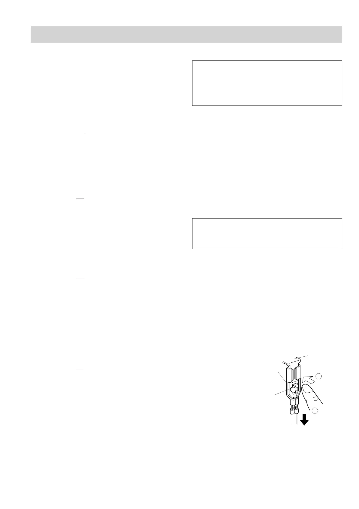
CONNECTOR REMOVAL
Figure C-1. Positive lock
®
connector
1. CARRY OUT 3D CHECKS.
2. Push the lever of positive lock
®
connector.
3. Pull down on the positive lock
®
connector.
CAUTION: WHEN YOU (SERVICE ENGINEERS) CON-
NECT THE POSITIVE LOCK
®
CONNEC-
TORS TO THE TERMINALS, CONNECT
THE POSITIVE LOCK
®
SO THAT THE LE-
VER FACES YOU .
6. Remove one (1) screw holding capacitor holder to the
oven cavity rear plate.
7. Release the capacitor holder from the fan duct.
8. Remove the high voltage capacitor from the capacitor
holder.
9. Disconnect the high voltage wire B and the high voltage
rectifier assembly from the high voltage capacitor.
10.Disconnect the high voltage rectifier assembly from the
high voltage wire B.
11.Now, the high voltage rectifier assembly and the high
voltage capacitor should be free.
CAUTION: WHEN REPLACING HIGH VOLTAGE
RECTIFIER ASSEMBLY, ENSURE THAT
THE CATHODE (EARTH) CONNECTION
IS SECURELY FIXED TO THE CAPACI-
TOR HOLDER WITH AN EARTHING
SCREW.
Terminal
Push
Pull down
1
2
Lever
Positive lock®
connector
COMPONENT REPLACEMENT AND ADJUSTMENT PROCEDURE