R-775(W)R-785(AL) - 12
CAUTION: BEFORE REPLACING A BLOWN FUSE F2
F8A, TEST THE MONITORED LATCH
SWITCH SW1 AND MONITOR SWITCH
SW3 FOR PROPER OPERATION. (REFER
TO CHAPTER “TEST PROCEDURE”).
FUSE F1 20A 250V
If the wire harness or electrical components are short-
circuited, this fuse F1 blows to prevent an electric shock or
fire hazard.
FUSE F2 F8A 250V
1. If the wire harness or electrical components are short-
circuited, this fuse blows to prevent an electric shock or
fire hazard.
2. The fuse also blows when the monitored latch switch
SW1 remains closed with the oven door open and
when the monitor switch SW3 contact (COM-NC)
closes.
3. The fuse also blows when the asymmetric rectifier,
H.V. rectifier,.H.V. wire harness, H.V. capacitor,
magnetron or secondary winding of high voltage trans-
former is shorted.
TC TRANSFORMER
T/C transformer converts A.C. line voltage into low voltage
to drive the control unit.
THERMAL CUT-OUT TC1 125˚C (MG)
This thermal cut-out protects the magnetron against over-
heat. If the temperature goes up higher than 125˚C be-
cause the fan motor is interrupted or the ventilation open-
ings are blocked, the thermal cut-out TC1 will open and
line voltage to the high voltage transformer T will cut off
and operation of the magnetron MG will be stopped. The
defective thermal cut-out must be replaced with a new
one.
THERMAL CUT-OUT TC2 145˚C (OVEN)
This thermal cut-out protects the oven against the over-
heat during grill cooking, convection cooking or dual
(combination) cooking. If the temperature rises above
145˚C because the fan motor is interrupted, the air inlet
duct is blocked or the ventilation openings are obstructed,
the thermal cut-out opens and switches off all the electrical
parts. When the cools itself down to the operating tem-
perature of 115˚C, the contacts of the thermal cut-out will
close again.
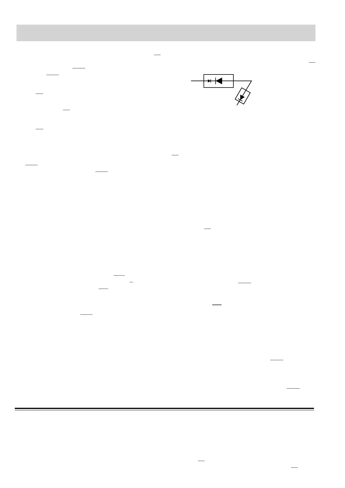
ASYMMETRIC RECTIFIER
The asymmetric rectifier is solid state device that prevents
current flow in both directions. It prevents the temperature
rise of the high voltage transformer by blowing the fuse F2
F8A when the high voltage rectifier is shorted.
The rated peak reverse voltage of D1 of the asymmetric
rectifier is 6 KV The rated peak reverse voltage of D2 of the
asymmetric rectifier is 1.7 KV. D1 and D2 of the asymmet-
ric rectifier or high voltage rectifier are shorted when the
each peak reverse voltage goes beyond the each rated
peak reverse voltage. (The process of the blowing the fuse
F2 F8A.)
1. The high voltage rectifier is shorted by some fault when
microwave cooking or dual cooking.
2. The peak reverse voltage of D2 of the rectifier goes
beyond the rated peak reverse voltage 1.7 KV in the
voltage doubler circuit.
3. D2 of the rectifier is shorted.
4. The large electric currents flow through the high volt-
age winding of the high voltage transformer.
5. The large electric currents beyond 8A flow through the
primary winding of the high voltage transformer.
6. The fuse F2 F8A blows by the large electric currents.
7. The power supplying to the high voltage transformer is
cut off.
NOISE FILTER
The noise filter assembly prevents radio frequency inter-
ference that might flow back in the power circuit.
TURNTABLE MOTOR TTM
The turntable motor rotates the turntable.
FAN MOTOR FM
The fan motor drives a blade which draws in external cool
air. This cool air is directed through the air vanes surround-
ing the magnetron and cools the magnetron. This air is
channelled through the oven cavity to remove steam and
vapours given off from heating food. It is then exhausted
through the exhausting air vents of the oven cavity.
TOP GRILL HEATING ELEMENT GH1
The grill heating element is provided to brown the food and
is located on the top of the oven cavity.
BOTTOM GRILL HEATING ELEMENT GH2
The grill heating element is provided to brown the food and
is located at the base of the oven cavity.
D2 D1
ASYMMETRIC
RECTIFIER
HIGH VOLTAGE
RECTIFIER
TROUBLESHOOTING GUIDE
When troubleshooting the microwave oven, it is helpful to follow the Sequence of Operation in performing the checks.
Many of the possible causes of trouble will require that a specific test be performed. These tests are given a procedure
letter which will be found in the “Test Procedure” section.
IMPORTANT: If the oven becomes inoperative because of a blown fuse F2 (F8A) in the monitored latch switch - monitor
switch circuit, check the monitored latch switch and monitor switch before replacing the fuse F2 (F8A).
FUNCTION OF IMPORTANT COMPONENTS