Service and Maintenance Manual 3-90 960714-02B © 2007 I2407
SECTION 3 – COMPONENT REPAIR
PRINTHEAD CRADLE ASSEMBLY
PRINTHEAD POSITION MOTOR (con’t)
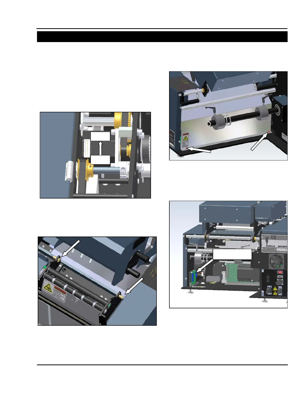
4. If the motor is not turning, unplug the motor
cable and check for continuity. Using a Digital
Volt/Ohm Meter (DVOM) set to test for
continuity, probe between pins 1 & 5, 2 & 6, 3
& 7, and 4 & 8. If the motor passes all
continuity checks, the motor is functioning
properly.
5. Remove the rear motor cover.
6. Locate the printhead position stepper drive.
Figure 3-220. Printhead Position Motor Pins
Figure 3-221. Motor Cover Front Screws
Figure 3-222. Motor Cover Rear Screws
Figure 3-223 Printhead Position Stepper Drive