Service and Maintenance Manual 3-140 960714-02B © 2007 I2407
SECTION 3 – COMPONENT REPAIR
JAW POSITION SENSORS
The jaw position sensors communicate to the
machine the location of the pressure jaw,
determining the speed at which the jaw is closing.
Jaw position is determined by two sensors, the first
called “near-home” and the second called “home.”
Some of the procedures in this section require that
the electrical power to the machine remain ON.
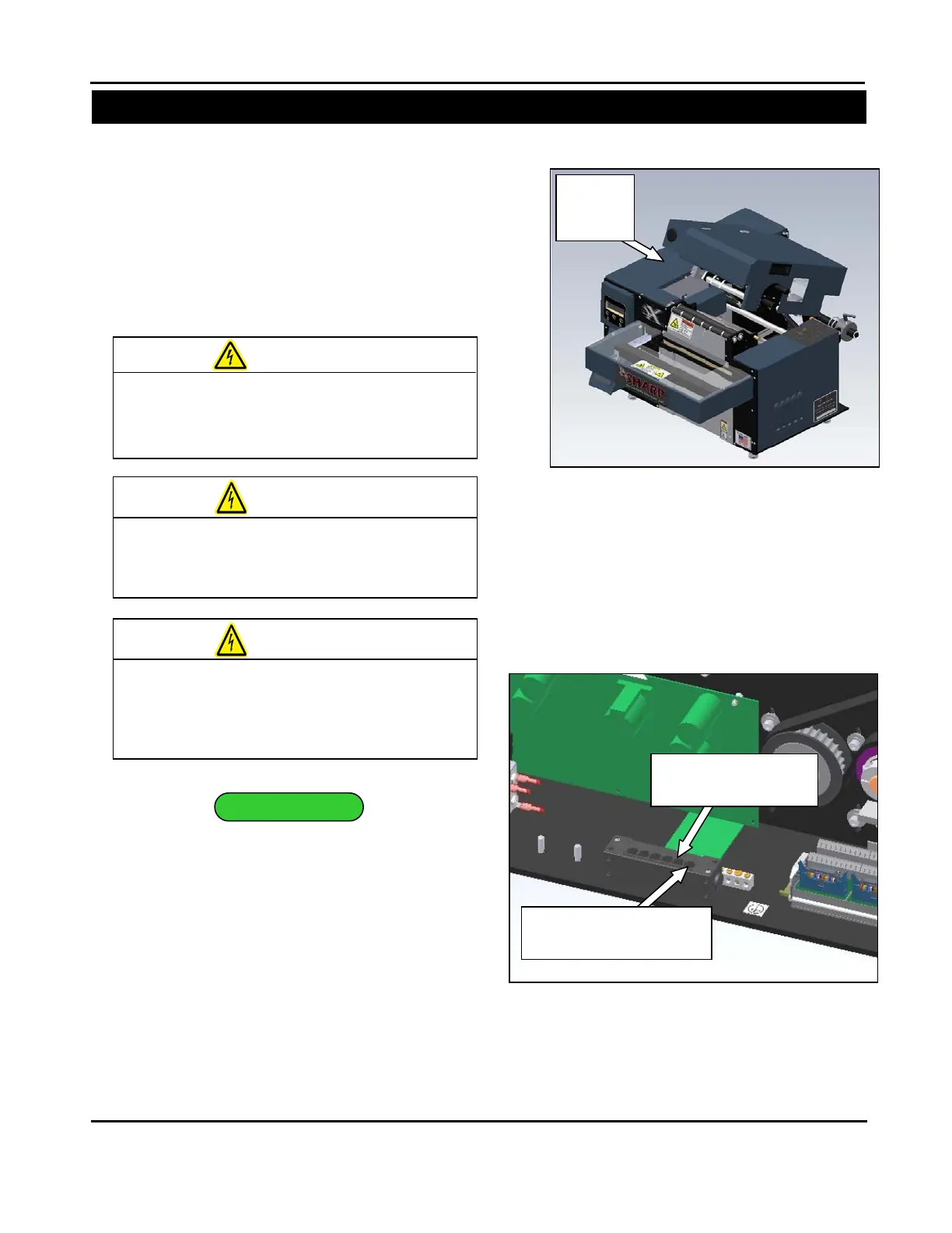
1. Remove the outside frame guard (Figure 3-
356).
2. Locate the 6-positon junction box. Ensure the
plugs are fully inserted into the ports. The “near
home” sensor will be in the receptacle numbered ‘1’
and the “home” sensor will be in receptacle ‘2’
(Figure 3-357).
USE EXTREME CAUTION WHILE SERVICING
A MACHINE WHILE POWER IS APPLIED.
UNEXPECTED MACHI
NE STARTUP CAN
CAUSE SERIOUS INJURY.
DO NOT ATTEMPT TO SERVICE THE
MACHINE DURING NORMAL OPERATION.
KEEP HANDS AND ARMS CLEAR OF
MOVING PARTS.
COMPONENTS WITH POWER APPLIED TO
TROUBL
ESHOOTING TECHNIQUES TO
AVOID ELECTRICAL SHOCK.
Figure 3-356. Guard Identification
Frame
(Receptacle 2)
Plug (Receptacle 1)
Figure 3-357.Jaw Position Sensor Plugs