Service and Maintenance Manual 3-141 960714-02B © 2007 I2407
SECTION 3 – COMPONENT REPAIR
JAW POSITION SENSORS (con’t)
4. Locate the PLC. While watching the inputs
labeled ‘X0’ and ‘X5”, pass a metal object
within .125” of the sensors. When activating
the forward (near home) sensor, the indicator
light labeled ‘X0’ on the PLC should illuminate.
Activating the rear (home) sensor should
illuminate the ‘X5’ indicator light. If the PLC
does not illuminate when either sensor is
activated, that sensor is faulty and needs
replacement.
Setting the pressure bar sensors to the proper
position requires the use of a setup jig, which can
be ordered from Sharp Packaging Systems Inc.
(Part Number 708709-01)
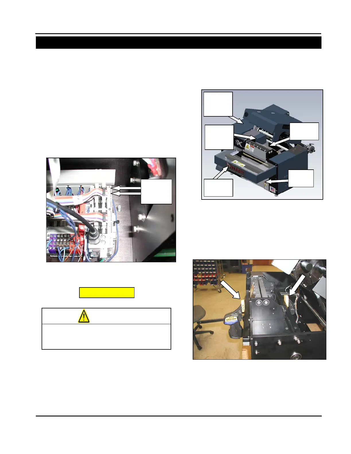
1. Remove the guards identified in Figure 3-371.
2. Fully slide the pressure bar in, and apply a
clamp between the pressure bar and rear
surface of the horizontal mounting plate. The
clamp should go underneath the horizontal
mounting plate as shown in Figure 3-360. This
will position the jaw in its sealing location.
and ‘X5’
Figure 3-360. Clamping the Pressure Jaw for
Setting Sensors
Figure 3-359. Guard Identification
Frame
Sealer
Always remove electrical power from the
SX
prior to performing any maintenance