5
3. About the Device
The Device is a DIN rail mountable smart switch with potential-free contacts. It controls on/off
function for one electrical device (with load up to 16 A), e.g., bulb, ceiling fan, IR heater,
electrical locks, garage doors, irrigation system, etc. and it is compatible with push-buttons and
switches (default).
If the SW (SW1) is configured as a switch, each toggle of the switch will change the output O
(O1) state to the opposite state - on, off, on, etc. If the SW (SW1) is configured as a push-button
in the Device settings, each press of the push-button will change the output O (O1) state to the
opposite state - on, off, on, etc.
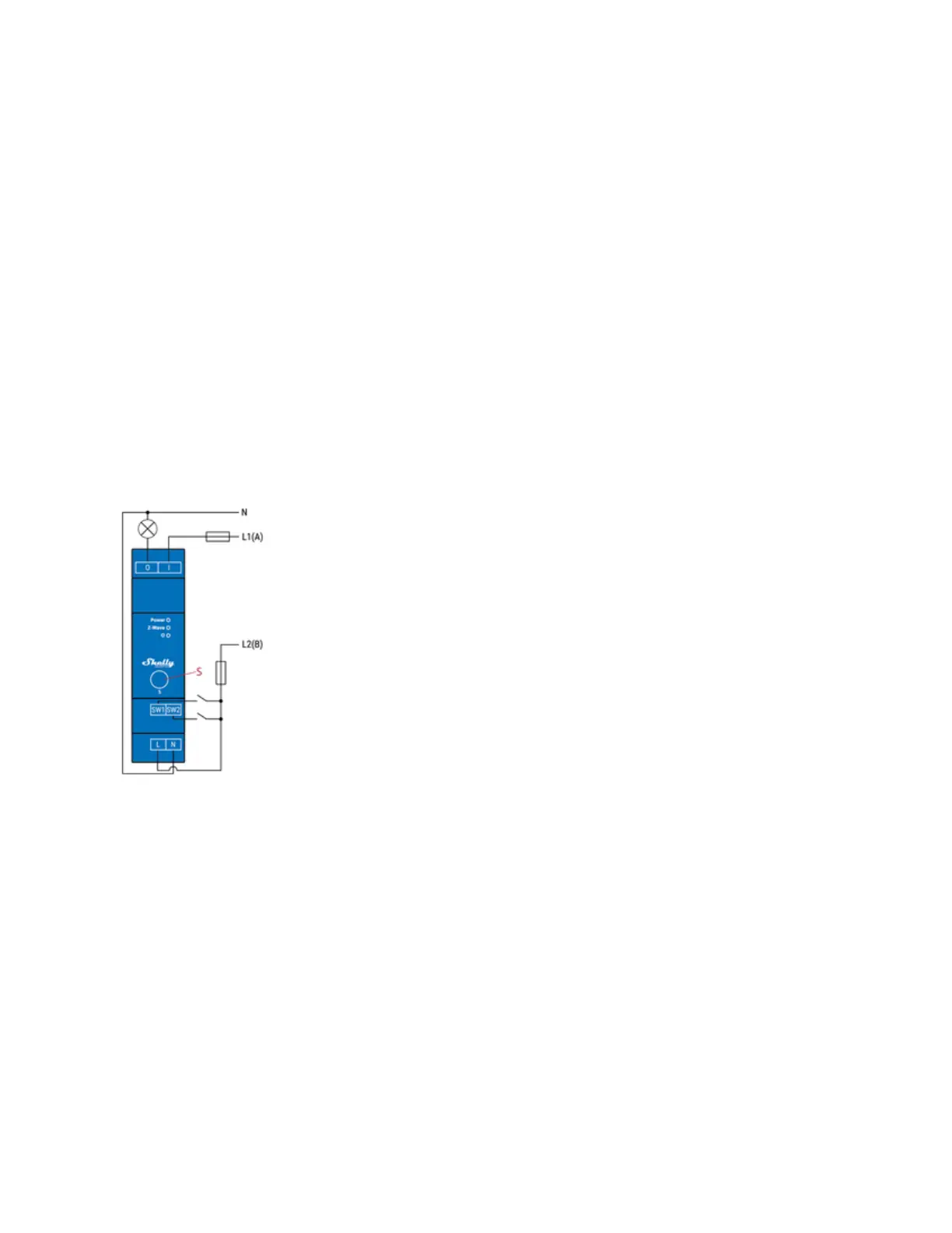
4. Electrical diagrams 110-240 V AC
Connecting to the power grid with power supply 110-240 V AC (Fig. 1).
Fig. 1
Device terminals:
• N: Neutral terminal
• L: Live terminal (110-240 V AC)
• SW (SW1): Input terminal for switch/push-button controlling O (O1)
• SW2: Input terminal for switch/push-button
• I: Input terminal for Load circuit
• O (O1): Output terminal for Load circuit (1)
Wires:
• N: Neutral wire
• L1(A): Load circuit Live wire (110-240 V AC)
• L2(B): Device power supply Live wire (110-240 V AC)
Button: S: S button