18
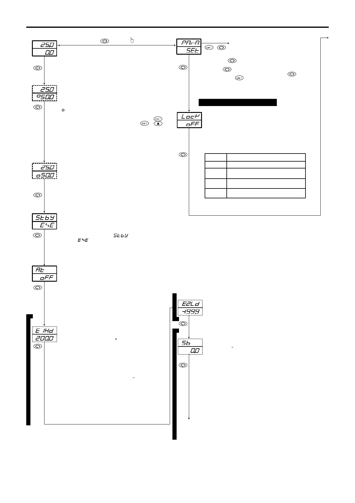
6. Explanation of Screen Group and Setting
holding down the key calls the last screen, i.e., the PV
is the first setting screen, appears. Pressing the key while
When the key is pressed, the keylock setting screen, which
Pressing the key for 3 seconds continuously on the basic
For switching auto to manual and vice versa, the key
Set either the control standby ( ) or
For details, see Section 5-5 (2).
is pressed continuously for 3 seconds or + key
on the output 1 or output 2 screen.
Initial value: Lower limit value of measuring range
Setting range: Within measuring range (within SV limiter)
A measured value (PV) is displayed on the top and the bottom is
for display and setting of a target set value (SV).
For details, see Section 5-5 (1).
A measured value (PV) is displayed. The bottom is for
monitoring of the control output value of output 1 in the automatic
mode and for changing a set value in the manual mode.
Manual output setting range: 0.0 – 100.0%
(within output 1 limiter)
Output monitor screens (OUT1 and OUT2) and auto/manual
output
•
• When the output mode (auto or manual) of either output 1
or output 2 is changed, the output mode of the other is also
changed.
• When the output is manual the Man lamp flashes.
For details, see Section 5-5 (2).
A measured value (PV) is displayed. The bottom is for
monitoring of the control output value of output 2 in the automatic
mode and for changing a set value in the manual mode.
Manual output setting range: 0.0 – 100.0%
(within output 2 limiter)
The screen appears only if the optional function of output 2 is added.
Initial value: OFF
Setting range: OFF, ON
AT is executed when ON is selected and is released when OFF is
selected. This screen does not appear during manual output and
when OFF is set for proportional band (P) of output 1.
While AT is being executed, key operation other than for
releasing AT, setting keylock and switching a communication
mode is not possible.
For AT action, see Section 5-5 (3).
Initial value:
Higher limit deviation value 2000 digit
Lower limit deviation value
1999 digit
Outside higher/lower deviations or within deviations:
2000 digit
Higher limit absolute value:
Higher limit value of measuring range
Lower limit absolute value:
Lower limit value of measuring range
Setting range:
Higher limit deviation value or lower limit deviation value:
1999 – 2000 digit
Outside higher/lower limit deviations or within deviations:
0 – 2000 digit
Higher limit absolute value or lower limit absolute value:
Within measuring range
This screen is displayed when the optional event function
is added and alarm code is assigned to Hd – LA and the action
point of the assigned alarm type is set on it.
For details, see Section 5-5 (5).
0-0
1-0
1-57
1-1
Basic screen
Output 1 (OUT1) monitor screen0-1
0-2
0-3
0-5
0-6
0-7
Output 2 (OUT2) monitor screen
STBY (standby) action control screen
0-4
AT (auto tuning) action control screen
Initial value: EXE
Setting range: STBY, EXE
This screen is only for monitoring when STBY is selected
on the 1-35 DI mode setting screen.
execute ( ).
For STBY, see Section 5-5 (4).
Event 1 (EV1) set value setting screen
To the 0-6 screen
To the 1-2 screen
To the
1-2 screen
0-3
screen calls this screen. There is no item to be set on this screen.
display at standby setting screen.
Initial value: OFF
Setting range: OFF, 1, 2, 3
Lock items which you don't want to be changed. Data are unable
to be changed on locked screens.
Select OFF to release the lock.
Initial screen
+ To the PV display at standby
setting screen
Key lock setting screen
Release of lock (All data allowed to be changed.)
Keylock for all screens except the screen group 0
and communication mode.
Keylock for all screens except basic screen and
communication mode.
Keylock for all screens except communication
mode.
The following table shows lock numbers
and ranges to be locked:
Lock No. Range to be locked
OFF
1
2
3
The above description of the 0-5 screen applies to the 0-6
screen, only with a change of EV1 to EV2.
Initial value: 0 digit
Setting range:
1999 – 5000 digit
This screen is displayed when the optional DI, set value bias
function is selected. A set value is effective while the SB,DI
terminals are shorted and it is added to or reduced
from the set value.
When an SB is effective, the monitor LED lamp SB/COM lights.
Event 2 (EV2) set value setting screen
Set value bias (SB) setting screen
To the 0-0 basic screen
3 seconds
(1) Setting of keylock
When event option is not selected, 0-7 is displayed.
When Set value bias of DI option is not selected, 0-0 is displayed.
 Loading...


