29
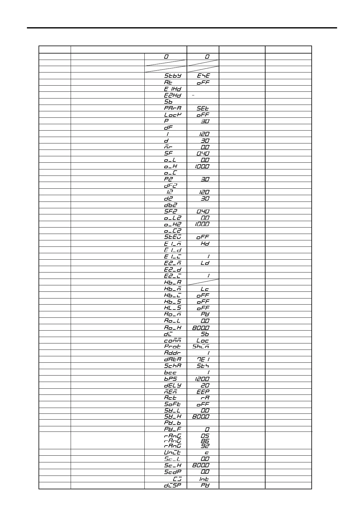
10. Record of Parameter Setting
For convenience sake, recording set values and selected items is recommended.
The initial values are of Code 05 (K)
( )
( )
( )
( )
Input scaling decimal point position
Input scaling lower limit
Input scaling higher limit
Screen No.
Parameter (Item)/screen display
Initial value
Setting/Selection
Record
Basic screen
Output 1 monito
Output 2 monito
T action
Event 1 set value setting
Event 2 set value setting
Set value bias setting
Initial screen
Keylock setting
Output 1 proportional band setting
Output 1 hysteresis
Output 1 integral time
Output 1 derivative time
Output 1 manual reset
Output 1 target value function
Output 1 lower limit output limite
Output 1 higher limit output limite
Output 1 proportional cycle time Y: 30, P: 3
2000 digit
1999digit
0 digit
20 digit
20 digit
0 digit
5 digit
5 digit
0 digit
Y: 30, P: 3
Output 2 proportional band setting
Output 2 hysteresis
Output 2 integral time
Output 2 derivative time
Output dead band
Output 2 target value function
Output 2 lower limit output limite
Output 2 higher limit output limite
Output 2 proportional cycle time
Event 1 type
Event 1 hysteresis
Event 1 standby action
Event 2 type
Event 2 hysteresis
Event 2 standby action
Heater current monito
Heater break/loop alarm
Heater break/loop alarm standby
Heater break alarm value
Heater loop alarm value
nalog output type
nalog output scaling lower limi
nalog output scaling higher limit
DI mode
Communication data format
Start characte
BCC operation type
Communication speed
Communication delay time
Communication memory mode
Control output characteristic
Soft start time
SV limiter lower limit value
SV limiter higher limit value
PV bias value
PV filter time
CJ external/internal switching
PV display at standby setting
Measuring range codes
Temperature unit
0-0
0-1
0-2
0-4
0-5
0-6
0-7
1-0
1-1
1-2
1-3
1-4
1-5
1-6
1-7
1-8
1-9
1-10
1-11
1-12
1-13
1-14
1-15
1-16
1-17
1-18
1-19
1-20
1-21
1-22
1-23
1-24
1-25
1-26
1-27
1-28
1-29
1-30
1-31
1-32
1-33
1-34
1-35
1-36
1-37
1-38
1-39
1-40
1-41
1-42
1-43
1-44
1-45
1-46
1-47
1-52
1-53
1-54
1-55
1-56
1-57
1-48
1-49
1-50
1-51
Universal:
V:
:
0
t.
E1Hd.
E2Hd.
Sb.
PArA.
Lock
P.
dF.
I.
d.
mr.
SF.
o-L.
o-H.
o-C.
P2.
dF2.
12.
d2.
db2.
SF2.
o-L2.
o-H2.
o-C2.
E1-m.
E1-d.
E1-i.
E2-m.
E2-d.
E2-i.
Hb-A.
Hb-m.
Hb-i.
Hb-S.
HL-S.
o-m.
o-L.
o-H.
Di.
dAtA.
SchA.
bcc.
bPS.
dely.
mem.
ct.
Soft.
SV-L.
SV-H.
PV-b.
PV-F.
rAnG.
rAnG.
rAnG.
Unit.
( )
( )
STBY action
0-3
STBY.
( )
( )
( )
( )
( )
( )
( )
( )
( )
( )
( )
( )
( )
( )
( )
( )
( )
( )
( )
( )
( )
( )
( )
( )
Event at STBY
StEV.
( )
( )
( )
( )
( )
( )
( )
( )
( )
( )
( )
( )
( )
( )
( )
( )
( )
( )
( )
( )
( )
( )
( )
( )
( )
( )
( )
( )
( )
Communication mode setting
comm.
Communication protocol
Communication address
Prot.
ddr.
( )
Cj.
Disp.
( )
( )
Sc-L.
Sc-H.
Scdp.
( )
( )
( )
( )
 Loading...


