8-7. Change in position of decimal point
Position of decimal point can be changed for linear input, TC of decimal point and RTD range.
You should keep in mind that operation differs for TC and RTD range when using linear input.
(1) Change in position of decimal point for linear input
Sets position of decimal point to be displayed.
If changing position of decimal point from 0.0 to 0.000, input scaling changes from 0.0
–
100.0 to 0.000
–
1.000.
(2) Change in position of decimal point of TC/RTD range
Display of places below the decimal point can be switched to display or mask.
If changing position of decimal point from 0.0 to 0, the places below the decimal point are rounded off before being masked.
If changing position of decimal point from 0 to 0.0, the places below the decimal point are displayed again.
Things requiring special attention
• Parameter values affected by range change (UNIT) also change similarly.
Example: If range is "5" (PV bias)
[Position of decimal point: 0.0] → Change → [Position of decimal point: 0] → Change again → [Position of decimal point: 0.0]
Measuring range lower limit value 0.0 0 0.0
Measuring range higher limit value 800.0 800 800.0
PV bias 20.5 21 21.0
* As described above, after changing the position of the decimal point, the value may not revert to the original value when
the position of the decimal point is changed back.
• When measurement range is changed, the position of the decimal point returns to the default position.
• If position of decimal point is 0, display accuracy is not guaranteed.
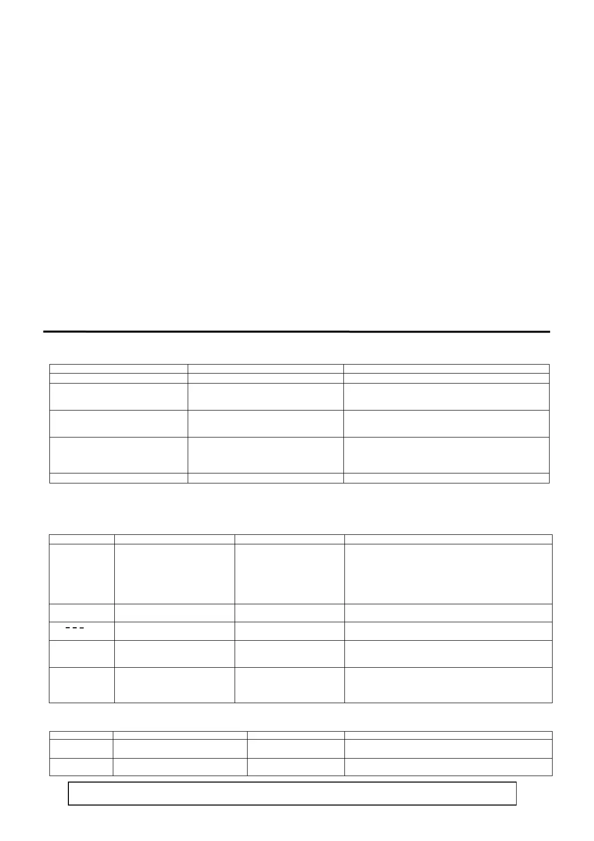
9. Causes and remedy of trouble and errors
9-1. Causes and remedy of trouble
Problem Cause Remed
Error message is displayed. See “Causes and remedy of errors.” See “Error Codes, Causes and Remedies.”
Displayed measured value (PV) seems to be
incorrect.
Set measuring range code is different from that of
input sensor / input signal.
Erroneous wiring to input terminals of sensor.
Check if set measuring range code is correct for input signal.
Cortect wiring to input terminals of sensor.
Front panel display goes off and does not
function.
Problem with power supply and/or wiring
connection.
Something is wrong with the instrument.
Inspect power supply / wiring connections and check wiring.
Inspect, repair or replace the instrument.
Keys do not work.
Key lock is in effect.
Communication is set to Com during
communication.
Something is wrong with the instrument.
Cancel key lock.
Set communication to local (Loc).
Inspect, repair or replace the instrument.
ON-OFF action of control output is too fast.
ON-OFF “hysteresis range” is too narrow.
Widen ON-OFF “hysteresis range. ”
9-2. Causes and remedy of errors
(1) Abnormal measured input
Screen displa
Problem Cause Remed
(HHHH)
Higher limit scaleover
Break in thermocouple input
wiring.
Break in R.T.D. input A wiring.
Input measured value exceeded
higher limit of measuring range
by 10%.
Check thermocouple input wiring for possible break. If there is
nothing wrong with wiring, replace thermocouple.
Check R.T.D. input A terminal wiring for possible break.
If there is nothing wrong with wiring, replace R.T.D.
For voltage or current input, check the measurement signal
transmission unit.
Check if set measurin
ran
e code is correct for in
ut si
nal.
LLLL
Lower limit scaleover Input measured value fell below lower
limit of measuring range by 10%.
Check for measurement input wiring for reverse polarity or possible
break.
(- - -)
Break in R.T.D. input wiring
Break in B wiring
Multiple break in ABB wiring
Check R.T.D. input ABB terminal wiring for possible break. If there
is nothing wrong with wiring, replace R.T.D.
(CJHH)
Higher limit scaleover of cold junction
(CJ) of thermocouple input
Ambient temperature has exceeded
80°C.
Reduce ambient temperature to the level provided in the environment
conditions for the product.
If ambient temperature has not exceeded 80°C, examine the controller.
(CJLL)
Lower limit scaleover of cold junction
(CJ) of thermocouple input
Ambient temperature has fallen
below -20°C.
Raise ambient temperature to the level provided in the environment
conditions for the product.
If ambient temperature has not fallen below -20°C, examine the
controller.
(2) Heater break/loop alarm errors
Screen display Problem Cause Remedy
(HbHH)
Heater current sensor CT input value has
exceeded 55.0A.
Excessive current
Reduce the current.
Inspect the controller.
(H
LL)
Something is wrong with the instrument. Something is wrong with the
instrument.
Inspect, repair or replace the instrument.
When the controller does not operate as intended and you suspect it may be broken, read the instruction manual and inspect once again. If there is something
wron
with the controller or there is somethin
ou do not understand
contact
our nearest Shimaden dealer.
 Loading...
