10
5-2. Display when power is applied
When power is applied, the initial screen displays each screen for about 1 sec. and switches to the basic screen of screen
group 0 as shown in the following figure.
Series name (i, k, l, m)
Input type (:thermocouple, :RTD, :Voltage [mV])
Indicates control output
OUT output type (: Contact, : SSR drive voltage, : Voltage, : Current)
Lower limit value of selected measuring range
Higher limit value of selected measuring range
0-0 basic screen, 0 screen group from here
Measured value (PV): Switches to screen for setting various functions by operation key from “0-0 Basic screen.”
Target set value (SV): For screen sequence, see parameter diagram on previous page.
5-3. Switching screens
Screen group 0: Screen group primarily set by end users
Screen group 1: Target set value setting screen group (multi SV)
Screen group 2: Screen group that sets PID constant
Screen group 3: Displayed if equipped with programming function (optional)
Screen group 4: Screen group that sets event and DI functions
Screen group 5: Initial setting screen group
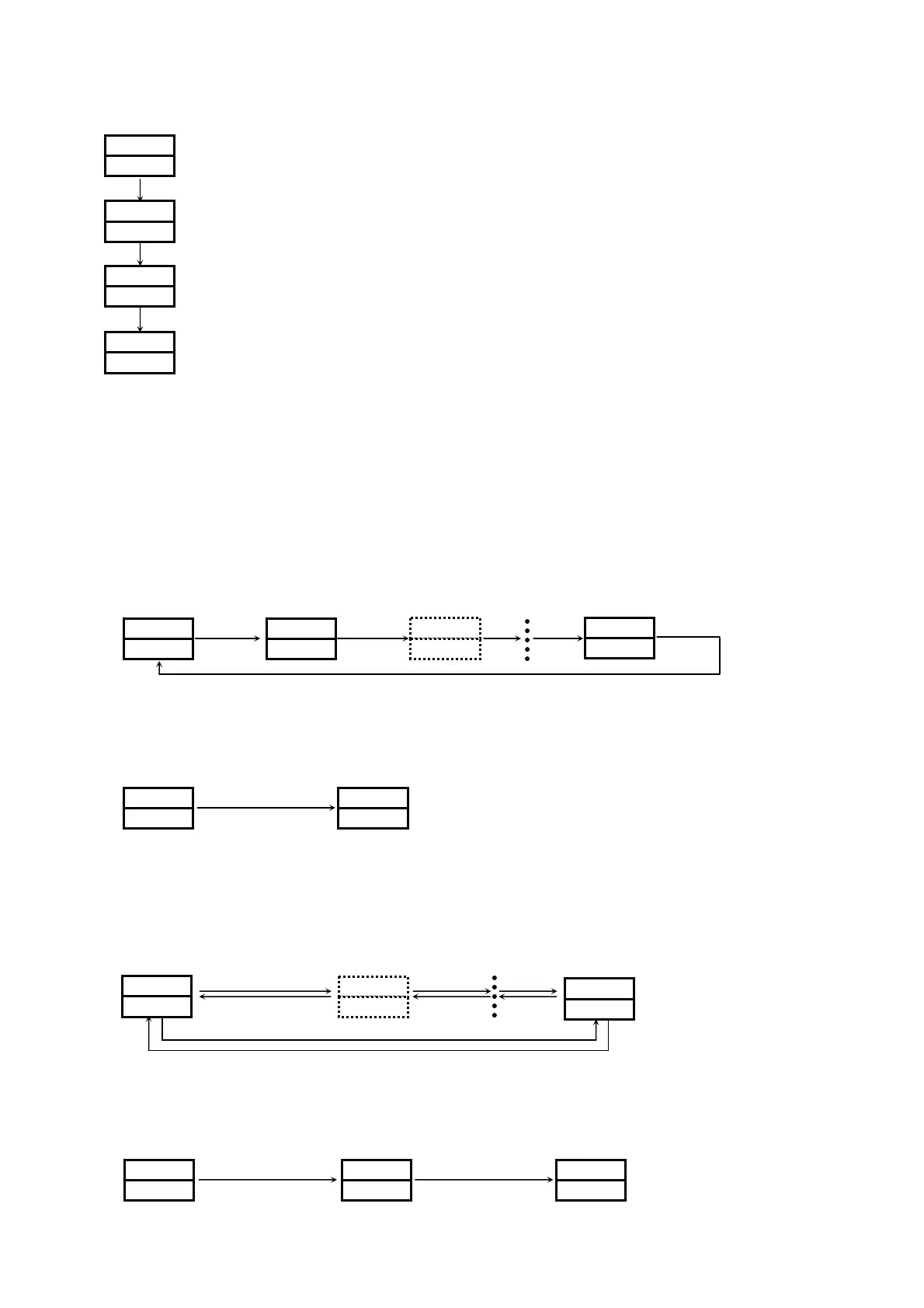
(1) Switching screens within screen group 0
Each time the Å key is pressed the screen display switches to the next screen.
If pressed when the last screen is displayed, returns to the “0-0 Basic screen.”
0-0 Basic screen 0-1 Standby setting 0-2 Monitoring output 0-13 Latching release
Å ÅÅ Å
(2) Switching between screen group 0 and screen group 1
Pressing the ģ key on the basic screen of screen group 0 switches to “1-0 FIX initial screen” of screen group 1.
0 screen group 1 screen group
0-0 Basic screen 1-0 FIX initial screen
ģ key
(3) Switching screens within screen group 1
Each time the Å key is pressed on the “1-0 FIX initial screen” in screen group 1, the screen display switches to the next
screen. If pressed when the last screen is displayed, returns to the “1-0 FIX initial screen.”
With screen group 1, each time the ģ+ Å keys (Ģ+ Å keys only on the initial screen) are pressed, the screen is
switched in the reverse direction.
1-0 FIX initial screen 1-1 FIX ON/OFF 1-8 Ramp ratio screen
Å ÅÅ
ģ+Å ģ+Å ģ+Å
Ģ+ÅÅ
(4) Switching to screen group 2
Pressing the ģ key on the “1-0 FIX initial screen” switches to the “2-0 PID initial screen” of screen group 2.
0 screen group 1 screen group 2 screen group
0-0 Basic screen 1-0 FIX initial screen 2-0 PID initial screen
ģ ģ
~
jm
h
jm
©mrh
jm
h
jm
~
~
jm
h
i
h
ikoh
jm
h
¦
i
~
(Displayed when event latching function is enabled.)
|
i
 Loading...