22
8. Explanation of functions
This section contains a description of operation not covered in “5-5. Screen group 0 setting.”
8-1. Events
(1) Alarm action
1) Deviation alarm
Sets alarm action points for deviation of measured values (PV) from target set values (SV).
For example, to trigger an alarm when measured value (PV) is 30°C or more and target set value is 20°C, the higher limit
deviation alarm is set to 10°C.
Or to trigger an alarm when measured value (PV) is 30°C or less and target set value is 100°C, the lower limit deviation
alarm is set to -70°C.
This is convenient if you want alarm action point to be in accordance with deviation from target set values. The setting
range is -1999–2000 digits.
2) Absolute value alarm
Sets alarm action point by absolute value. Higher limit absolute value alarm and lower limit absolute value alarm can be set
at any point within measuring range.
For example, to trigger an alarm when measured value reaches 50°C or higher, set the higher limit absolute value alarm to 50°C.
Or to trigger an alarm when measured value reaches 20°C or lower, set the lower limit absolute value alarm to 20°C.
3) Standby action
If event standby action is set to 1 (or 2), an event is not output even if the measured value is in the alarm action area (ON
area) when power is applied, standby is canceled, or target set value is changed.
Once outside the alarm action area (OFF area) and standby action is canceled, an event is output when it once again
enters the alarm action area.
4) Non-standby action
If event standby action is set to OFF and 3, an event is always output when the measured value is within the alarm action area.
5) Control mode
If standby action is set to 3, alarm is not triggered when scaleover occurs.
(2) Event standby action selection
The following are supplementary explanations of operation with “4-3 and 4-9 Event 1/2 standby action code setting screen”
of screen group 4.
1. If using event output as an alarm, set from 1 or 2 of standby action code table.
2. If using event output for control, set 3 (control mode). If 3 is set, however, event output remains OFF for abnormal input.
3. If set to 1, standby action functions when power is applied or standby is cancelled.
4. If set to 2, standby action functions when power is applied, when standby is canceled and when execution SV is changed.
Note 1: Standby action is canceled immediately if changed to OFF or 3 during standby action.
Note 2: When scaleover occurs, standby action is canceled.
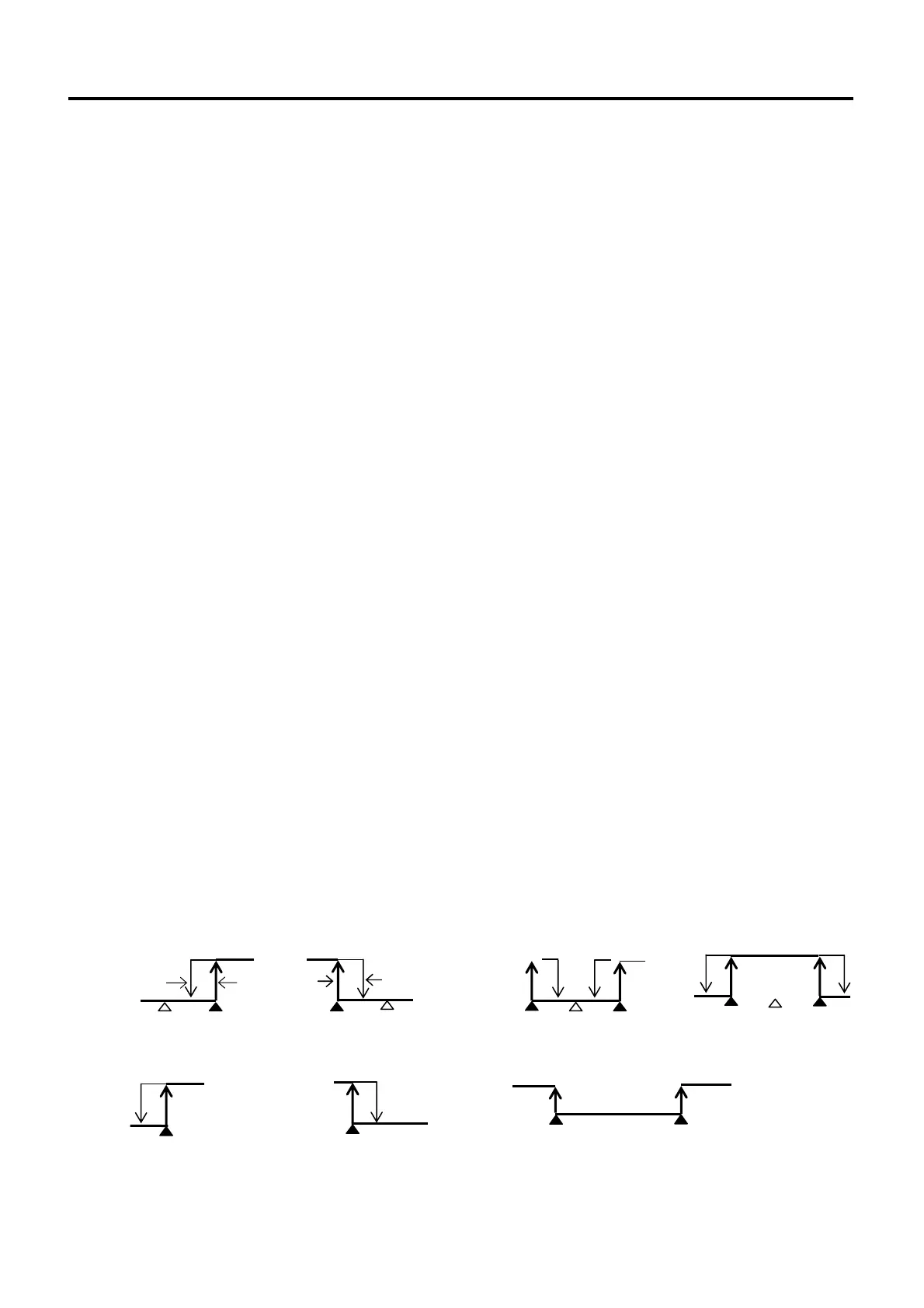
(3) Event selection alarm action diagrams
The following diagrams describe alarm actions selected for event (EV1/EV2).
䕧: SV value
ڸ: Alarm action point setting value
Action ON
Hysteresis
Action ON
Hysteresis
Action ON
Action ON
Action ON
Action ON Action ON
-10% ĸ PV value ĺ 110%
Action ON Action ON
: Higher limit deviation alarm
: Lower limit deviation alarm
: Outside higher/lower
limit deviation alarm
: Inside higher/lower
limit deviation alarm
|
: Higher limit absolute value alarm
|
: Lower limit absolute value alarm
: Scaleover
 Loading...

