23
(4) Control output inverted output
If equipped with contact output for control output, inverted output can be executed for control output by selecting i
(control output inverted output) for the event code. Output is, however, OFF for both control output and event when
the power is off.
Also, inverted output for control output can be executed as well during standby.
(5) Event status output action
1) (RUN) RUN signal: Output during program mode when the program is controlled by fixed
value control (FIX mode) action.
2) (STPS) Step signal: Output for 1 second each time step in program control execution
is completed.
3) (PTNS) Pattern signal: Output for 1 second each time pattern in program control execution
is completed.
4) ~ (ENDS) Program end signal: Output for 1 second when program control execution is completed.
(Output even if program is forcibly completed halfway.)
5) (HOLD) Hold signal: Output when holding (temporary halt of program) during program control.
6) (PROG) Program signal: Output when set to program mode.
7) ¦ (U_SL) Upslope signal: Output during upslope step execution during program control.
8) ¦ (D_SL) Downslope signal: Output during downslope step execution during program control.
9) | (GUA) Guarantee soak signal: Output when guarantee soak is engaged.
8-2. P.I.D.
(1) P (proportional action)
Sets percentage at which control output varies for measuring range. The size of control output varies in proportion to the
difference between PV value and SV value.
The slighter the proportional band is, the more intense output variation and proportional action are. If it is too slight, control
vibrates and the results of control are similar to ON-OFF action.
(2) I (integral time)
Function that corrects offset (constant deviation) produced by proportional band. The longer the integral time, the weaker
the corrective action and the shorter the time, the stronger the action is, but control may vibrate due to integral hunting.
(3) D (derivative time)
Enhances stability by estimating change in control output and suppressing integral overshoot.
The longer the derivative time, the stronger derivative action is, but control results may be similar to vibration.
(4) MR (manual reset)
During PID action, offset is automatically corrected by integration (“I”), but if “I” is OFF, offset is not corrected. If so, offset
can be corrected by manually increasing/decreasing output. This is called “manual reset.”
(5) SF (target value function)
This function determines the strength of the overshoot preventing function when operating expert PID.
Expert PID suppresses overshoot by conducting operation for predicting and canceling the amount of overshoot by
referring to values such as the PID value and the variation of PV value until the target set value (SV) (or the proportional
band) is reached. Target value function is effective only when there is an integral operation (PI, PID operation).
SF= OFF: Expert PID does not function and normal PID operates.
SF= 1.00: Minimize overshoot for expert PID control.
SF ĺ Small: Overshoot preventing function works limitedly.
SF ĺ Large: Overshoot preventing function works fully.
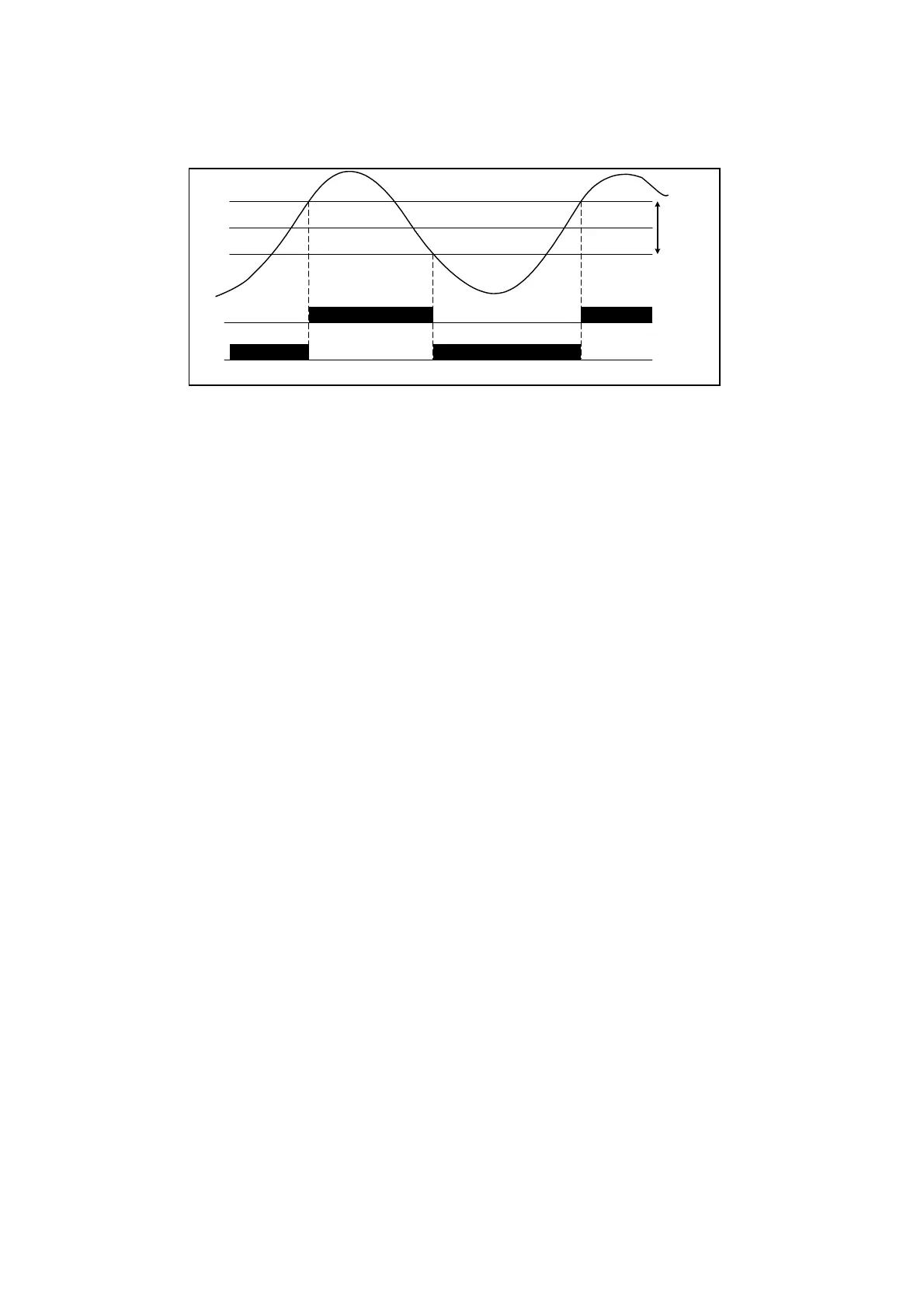
SV
Output 1
Hysteresis
OUT1
Event
PV
 Loading...

