6
3-4. Wiring
WARNING
Ɣ Be sure to turn off power before wiring. Failure to do so could result in electric shock.
Ɣ After wiring, do not touch terminal elements or other charged parts while conducting electricity.
Failure to do so could result in electric shock.
Take the following precautions when wiring:
1) Wire in accordance with the terminal layout of section 3-5 and the terminal arrangement table of section 3-6.
After wiring, check and make sure the wiring is correct.
2) Crimp-type terminals fit M3 screws. Use crimp-type terminals that are no wider than 6 mm.
3) For thermocouple input, use a compensating conductor that matches the type of thermocouple.
4) For RTD input, resistance for lead wires should be a maximum of 10ȍ per wire.
All 3 wires should have the same resistance.
5) Input signal wires must not be accommodated with a strong electric circuit in the same conduit or duct.
6) Using shielded wiring (single point grounding) is effective for static induction noise.
7) Making input wiring short and twisting at regular intervals is effective for electromagnetic induction noise.
8) For power supply, use wiring or cable with sectional area of at least 1 mm² that offers the same performance as 600 V
vinyl insulated wiring.
9) Securely fasten the terminal element screw. Fastening torque: 0.5 N·m (5 kgf·cm)
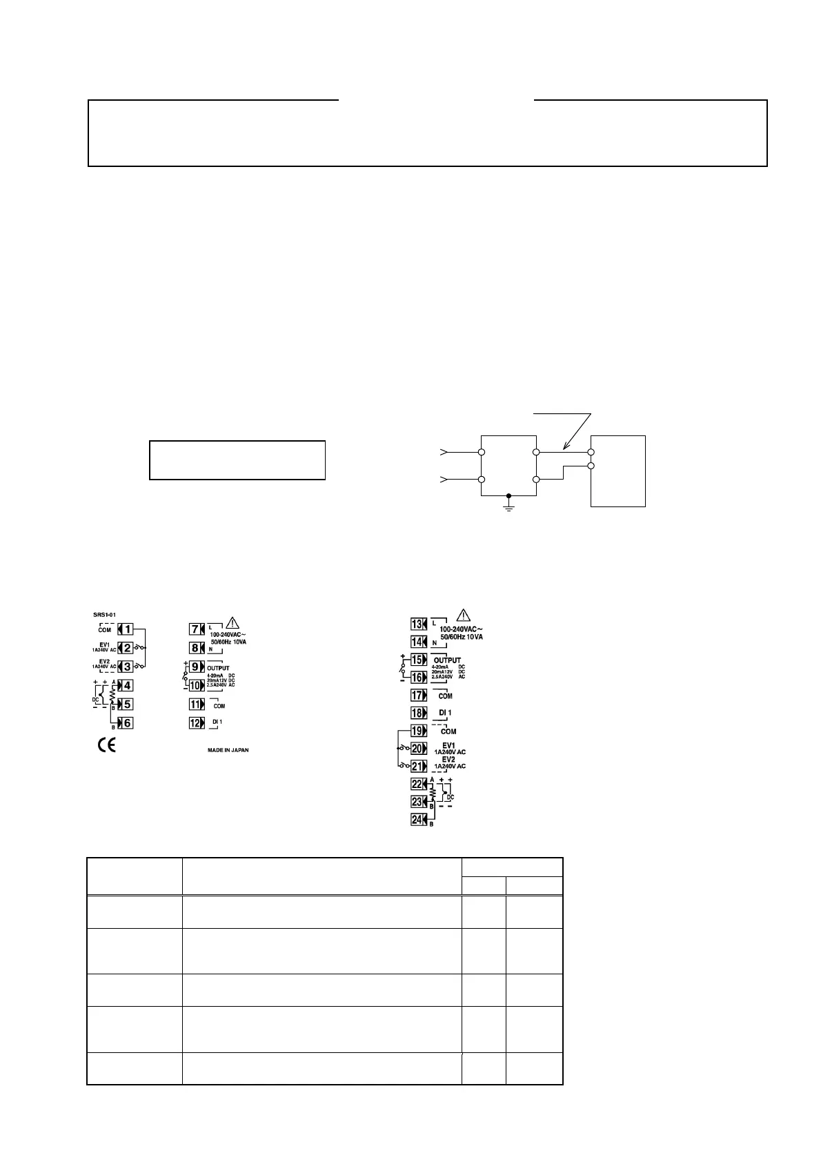
10) If the instrument appears to be easily affected by power supply noise, use a noise filter to prevent malfunctioning.
Mount the noise filter on the grounded panel and make the wire connection between the noise filter output and power
line terminals of the controller as short as possible.
3-5. Terminal layout
Wire in accordance with the following terminal layout and terminal arrangement table.
SRS1 SRS3/SRS4/SRS5
3-6. Terminal arrangement table
Name of
terminal
Description
Terminal No.
Note 1: With thermocouple/voltage
input, shorting across B and B
terminal will cause an error.
SRS1 SRS3/4/5
Power supply
100
240 V AC
100–240 V AC
7
8
13
14
Input
RTD: A, thermocouple/voltage: +
RTD: B, thermocouple/voltage: -
RTD: b
4
5
6
22
23
24
Control
output 1
Contac
: NO, SS
drive voltage/voltage/curren
:+
Contact: NO, SSR drive voltage/voltage/current: -
9
10
15
16
Event output
COM
EV1
EV2
1
2
3
19
20
21
External
control input/DI
COM
DI1
11
12
17
18
Recommended noise filter:
TDK RSEL-2003W
Noise filte
Make this wire short.
Controlle
100–240 V
C
50/60 Hz
IN OUT
100
240 V
C
Ground
 Loading...