34
Dealer’s Manual (SG-C7050-5V / SG-C7050-5R / SG-C7050-5C / SG-C7050-5D)
Return to index page
https://si.shimano.com/DM/CASG003
Click here for the latest Dealer's Manual
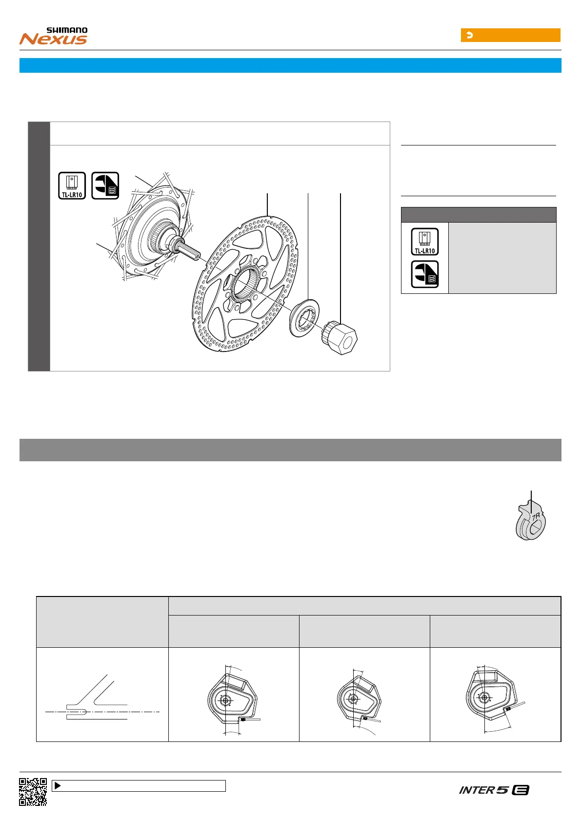
Installation of the disc brake rotor
Install the disc brake rotor as shown in the illustration.
Center lock type
(A) (B) (C)
(A)
Disc brake rotor
(B)
Disc brake rotor installation ring
(C)
TL-LR10
Tightening torque
40 N·m
Installation of the hub to the frame
Non-turn washer
Use non-turn washers to secure the internal geared hub and motor unit to the frame.
Non-turn washers are classified with a mark and main body color for easy identification. There are left and right types, and the right
type is normally used on the chain side.
Refer to the following to select the non-turn washer based on the shape of the motor unit and dropout to use.
Mark
MU-UR500
•
When the dropout is the reversed type
Dropout
Installation angle of non-turn washer and motor unit
5R (yellow)/
5L (brown)
6R (silver)/
6L (white)
7R (black)/
7L (gray)
11.5°
20°
21.5°