• This setting item is not indicated when Heater burnout alarm is
not added.
• Rating 5A : 0.0 to 5.0A Rating 20A: 0.0 to 20.0A
Rating 10A: 0.0 to10.0A Rating 50A: 0.0 to 50.0A
Loop break alarm action time setting
• Sets the action time to assess the Loop break alarm.
• Setting the value to 0 disables this function.
• When alarm and Heater burnout alarm are applied together,
the output is common.
• Setting range: 0 to 200 minutes
0 minutes
Loop break alarm action span setting
• Sets the action span to assess the Loop break alarm.
• Setting the value to 0 disables this function.
• When alarm and Heater burnout alarm are applied together,
the output is common.
• Thermocouple, RTD inputs: 0 to 150
( ) or 0.0 to 150.0 ( )
DC voltage and current inputs: 0 to 1500 (Decimal point place
follows the selection)
0
(Table 5.3-1)
Alarm action type Setting range
High limit alarm -(Scaling span) to scaling span
Low limit alarm -(Scaling span) to scaling span
High/Low limits alarm 0 to scaling span
High/Low limit range alarm 0 to scaling span
Process high alarm Scaling low limit value to scaling high limit value
Process low alarm Scaling low limit value to scaling high limit value
High limit alarm with standby -(Scaling span) to scaling span
Low limit alarm with standby -(Scaling span) to scaling span
High/Low limits with standby 0 to scaling span
Minimum
negative
setting value:
-199.9 or -1999
Maximum
positive
setting value:
999.9 or 9999
5.4 Auxiliary function setting mode 1
Character Name, Description, Setting range Default value
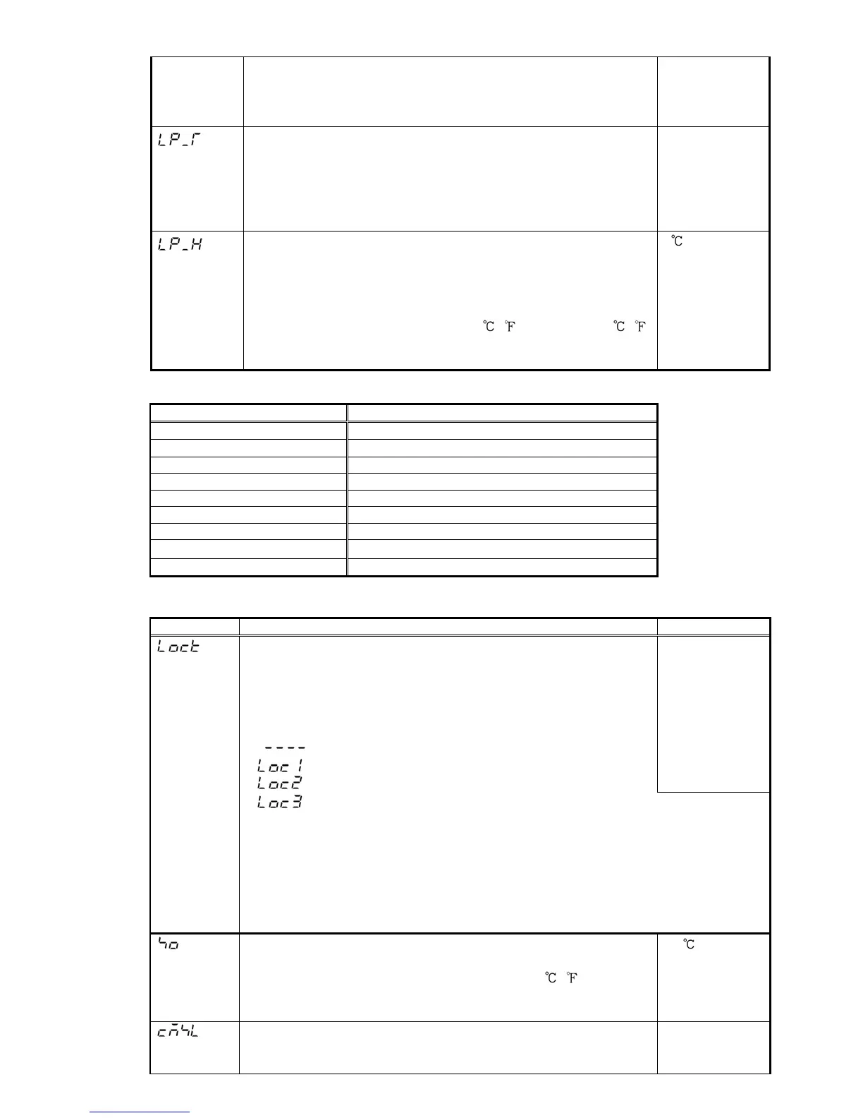
Setting value LOCK selection
• Locks the setting value to prevent setting errors.
The setting item to be locked is dependent on the designation.
• PID auto-tuning cannot be carried out when Lock1 or Lock2
is selected. Be sure to select LOCK 3 when our programmable
controller (with SVTC) is used together.
•
(Unlock) : All setting values can be changed.
(LOCK 1): None of setting values can be changed.
(LOCK 2): Only main setting mode can be changed.
Unlock
(LOCK 3): All setting values can be changed except Controller/Converter
function selection. But do not change each setting item of
auxiliary function setting mode 2.
Changed data reverts to their former value after power is
turned off because they are not saved in the non-volatile
memory. Lock 3 is suitable when our programmable
controller (with SVTC) is used together because it has noting
to do with memory life.
Sensor correction setting
• Sets the sensor correction value of the sensor.
• Thermocouple and RTD inputs: -100.0 to 100.0
( )
DC voltage and current inputs: -1000 to 1000 (Decimal point
place follows the selection.)
0.0
Communication protocol selection
• Selects communication protocol.
• This item is not indicated when [Option: C5] is not added.
Shinko protocol
 Loading...