-38-
Model W1849 (For Machines Mfd. Since 11/16)
SETUP
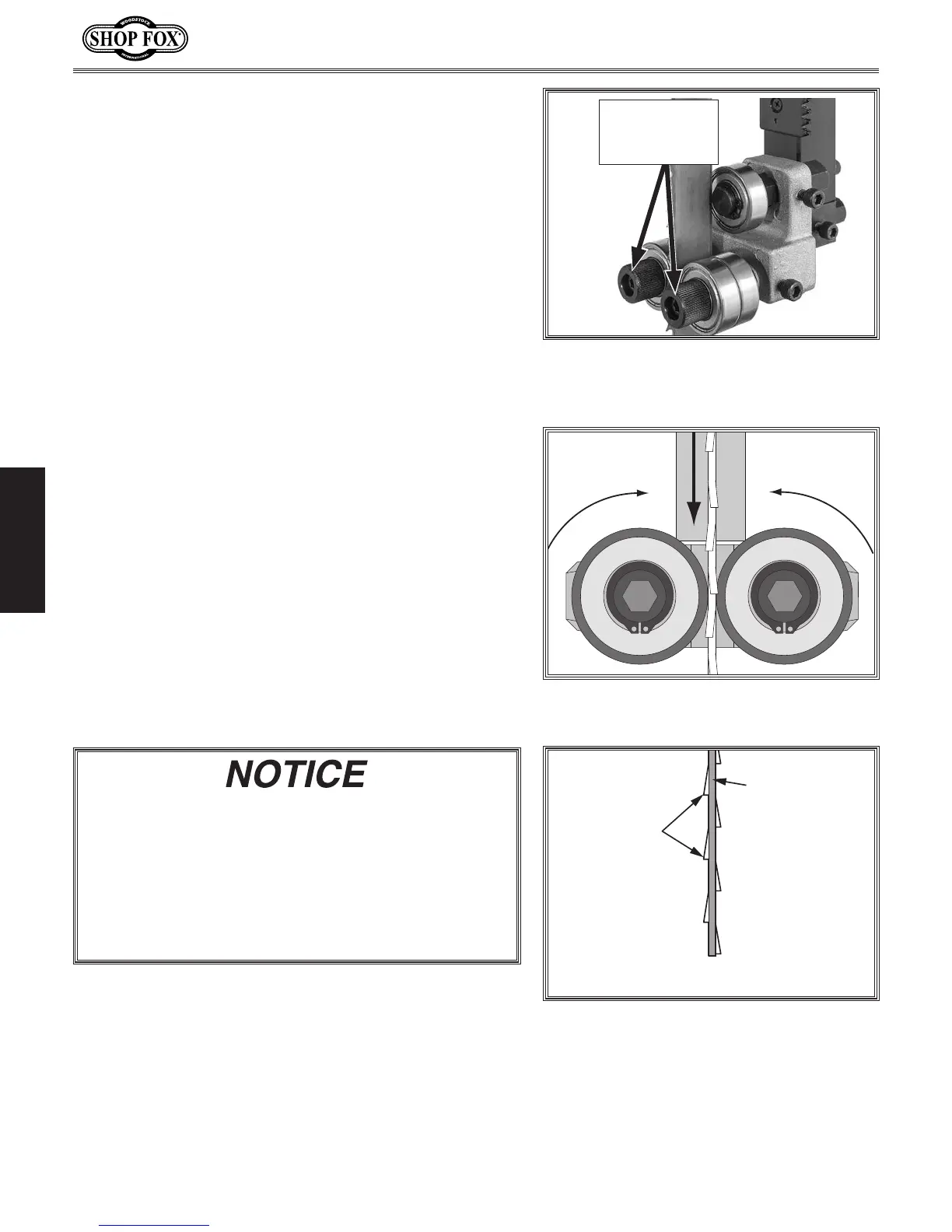
3. Loosen both guide bearing adjustment cap screws
(see Figure 55), then position guide bearings so they
are close to —but not quite touching—sides of blade.
Note: When the blade guide bearings are properly
adjusted, they should only rotate during cutting
operations, or when the blade is deflected to the
left or right (see Figure 56).
4. Retighten cap screws to secure settings. Rotate
blade by hand to check the setting, and, if
necessary, repeat Steps 3–4.
Figure 56. Blade guide bearings rotating
during cutting operation.
Figure 55. Location of upper guide bearing
adjustment cap screws (guide post cover
removed for clarity).
Guide Bearing
Adjustment
Cap Screws
Blade teeth are angled out slightly, protruding wider
than the blade thickness; this is known as blade
"tooth set" (see Figure 57). If angled out parts of
the teeth contact guide bearings during operation,
they will get bent inward, ruining the tooth set.
Therefore, the support bearing must be set to
prevent teeth from contacting guide bearings during
operation (refer to Page 37 for details).
“Tooth Set”
Wider Than
Blade Thickness
BladeThickness
Figure 57. Illustration of blade "tooth set."


 To Next Page