-7-
Model W1849 (For Machines Mfd. Since 11/16)
INTRODUCTION
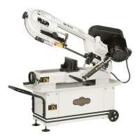
Guide Post
H. Guide Post Handwheel: Adjusts height of
guide post above workpiece, using a rack-
and-pinion system.
I. Guide Post w/Scale: Houses upper blade
guides and support bearing, and shields
operator from upper portion of blade.
Adjusts up or down as necessary to position
upper blade guides/support bearing as
close as possible to workpiece for maximum
cutting accuracy and minimum blade
exposure to operator. Scale on side of guide
post indicates height of upper blade guide
above table.
J. "Euro-Style" Upper Blade Guides &
Support Bearing: Supports blade above
workpiece during operations.
K. Guide Post Lock Knob: Secures guide post
in position after adjustment.
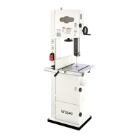
Blade Tension & Tracking
M
Figure 5. Blade tension scale, blade tension
handwheel, and tracking window.
M. Blade Tension Scale: Displays blade tension
using numbers 1–8. For reference purposes
only—after you have found the proper
tension for the particular blade installed.
N. Blade Tension Handwheel: Increases/
decreases blade tension (refer to Page 30
for more information).
O. Blade Tracking Window: Allows
monitoring/adjustment of blade tracking
without requiring w heel cover to be open
(refer to Page 27 for more information).
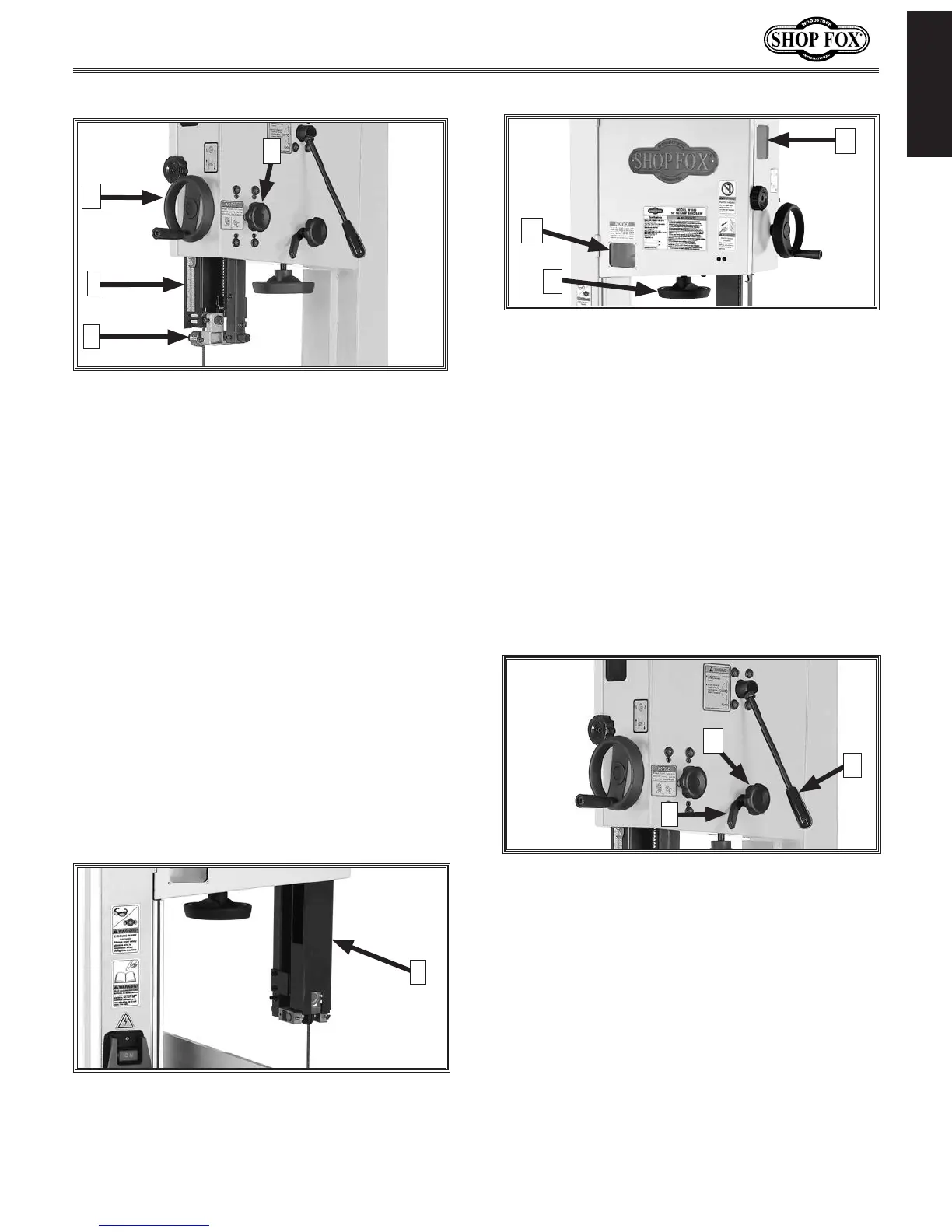
P. Tracking Control Lock Lever: Secures
position of blade tracking control knob.
Q. Tracking Control Knob: Sets tilt position of
upper wheel to set/control blade tracking
(refer to Page 27 for more information).
R. Blade Tension Quick-Release Lever:
Quickly releases blade tension to speed up
blade changes and prevent unnecessary
wear on blade and saw components when
not in use. Move UP to release blade
tension. Move DOWN to re-tension blade.
Figure 6. Blade tracking controls and blade
tension quick-release lever.
P
Q
R
N
L. Hinge-Open Blade Cover: Opens for blade
changes and upper blade guide adjustments
(refer to Page 50).
Figure 4. Hinge-open blade cover.
L
Figure 3. Guide post controls.
K
H
I
J
O
 Loading...