- 26 -
A1
A2
B1
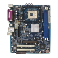
Jumpers
JP16 : Clear CMOS
JP3 : BIOS Write Protection
Back-Panel Connectors
KB : PS/2 Keyboard
MS : PS/2 Mouse
USB : 2 USB (Universal Serial Bus)
COM1 : Serial Port 1 (DB9 male)
COM2 : Serial Port 2 (DB9 male)
PRINTER : Parallel Port (DB25 female)
LINE-OUT : Line-Out Port
LINE-IN : Line-In Port
MIC-IN : Mic-In Port
GAME/MIDI : MIDI/Game Port
Front-Panel Connectors (JP7, JP4 and JP5)
PWR PT : ATX Power On/Off Momentary Type Switch
EPMI : Hardware System Management Interface Momentary
Type switch
GLED : Green LED (ON when system stays in power saving mode)
HLED : IDE Drive Active LED
PLED : System Power LED
RST : Hardware Reset Switch
SPEAK : Housing Internal Speaker
JP4/JP5 : Extended USB Header (USB3~USB6)
Internal Peripherals Connectors
FDD : Floppy Disk Drive Interface
IDE1 : IDE Primary Interface (Dual-channel)
IDE2 : IDE Secondary Interface (Dual-channel)
Other Connectors:
JP6 : ATX Power (20-pin header)
FAN1 : CPU Fan Power
FAN2 : AGP Fan Power
FAN3 : System Fan Power
FAN4 : North Bridge Fan Power
B1
B2
B3
B3
B6
B7
B8
B4
B5
C2
C1
C3
C4
C5
C6
C7
C8
D1
D1
D1
E1
E2
E2
E2
E2