- 33 -
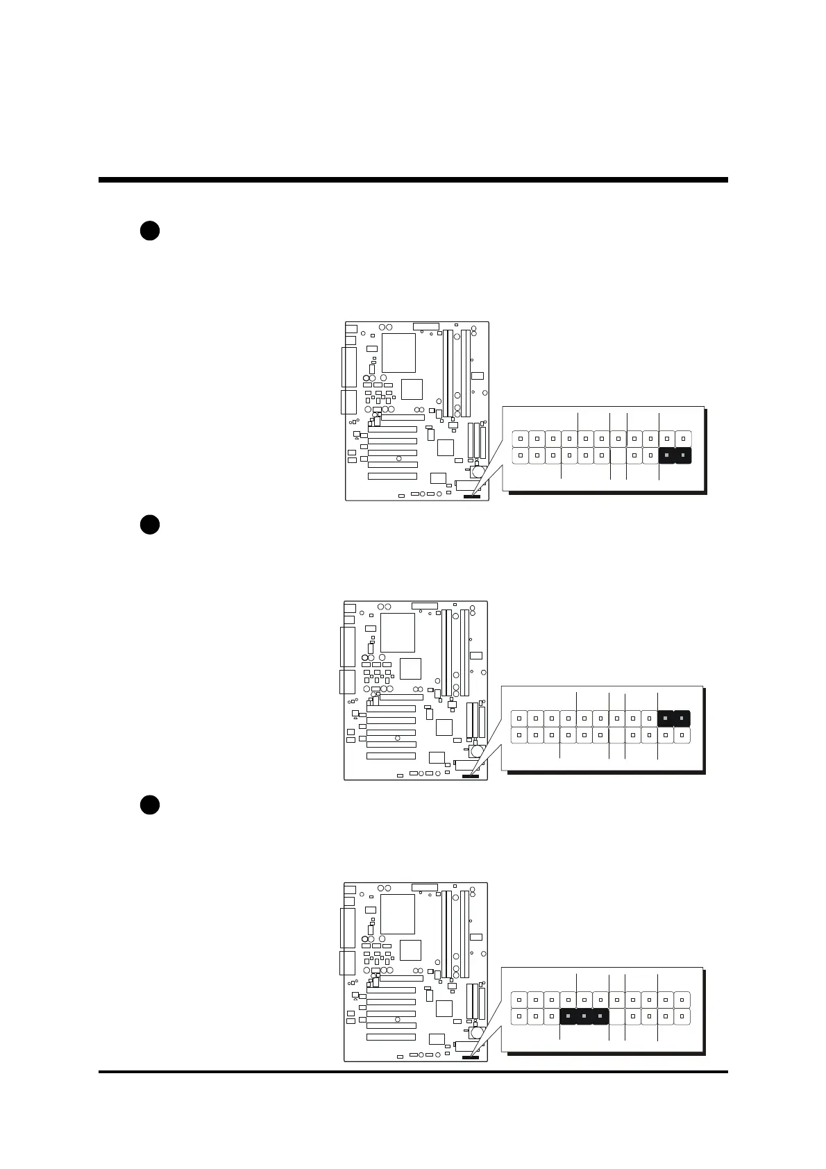
Green LED Connector (GLED)
The Green LED (GLED) indicates that the system is currently in one of the power
saving mode (Doze/Standby/Suspend). When the system resumes to normal
operation mode, the Green LED will go off. Attach a 2-pin Green LED cable to
GLED header.
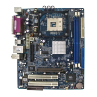
HDD LED Connector (HLED)
Attach the connector cable from the IDE device LED to the 2-pin HLED header.
The HDD LED lights up whenever an IDE device is active.
PWR LED Connector (PLED)
Attach the 3-pin Power-LED connector cable from the housing front-panel to
the PLED header on the mainboard. The power LED stays light while the sys-
tem is running.
C4
C3
C5
1
SPEAKER
GLED
+ -
- +
EPMI
Power
ON
HLED
1
SPEAKER
GLED
+ -
- +
EPMI
Power
ON
HLED
1
SPEAKER
GLED
+ -
- +
EPMI
Power
ON
HLED