12 of 34
SI-TEX Marine Electronics - SP120C Color Autopilot
Wiring Information
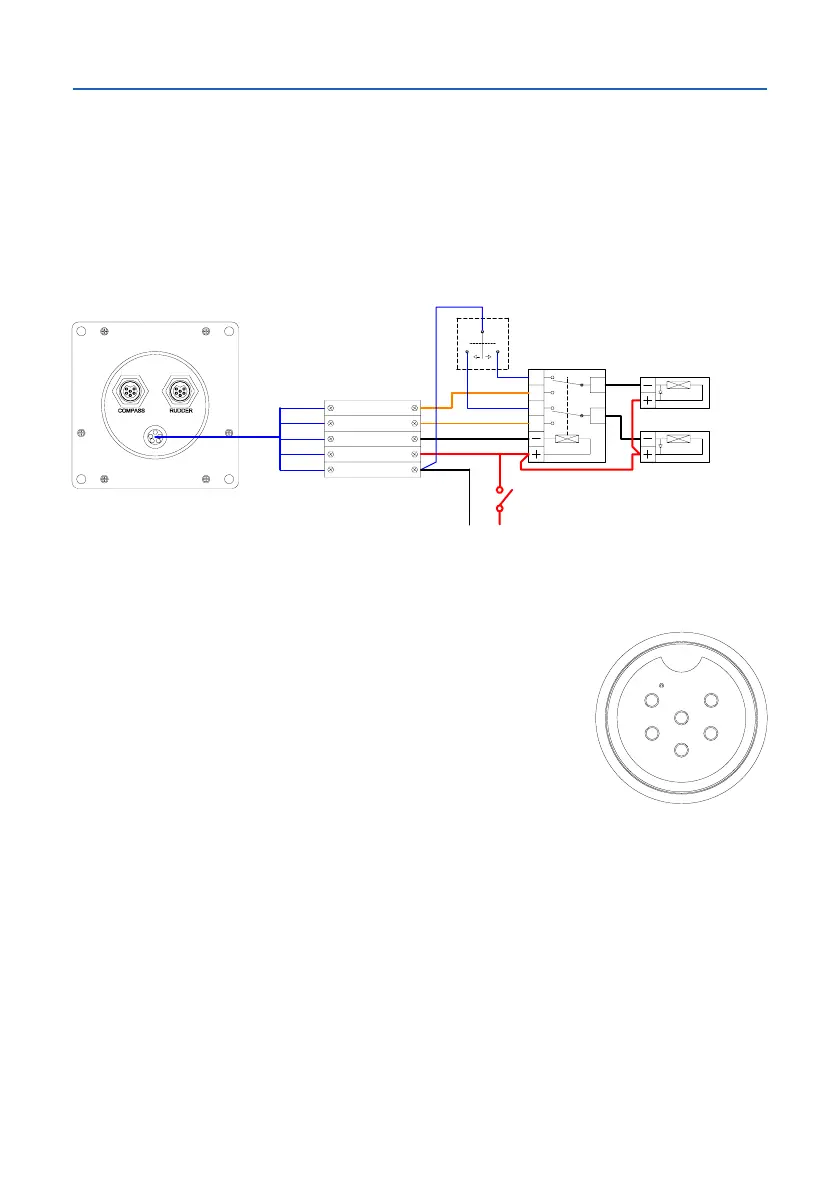
Solenoid Valves - Important Information
Ifanemergencyjogleveristtedthenthemotoroutputsmustbeisolated!to
prevent damage to the drivers. To isolate, a 2 pole change over relay must be
installed between the SP120C and the Solenoids, as per diagram below;
Also as a preventative measure to ensure voltage spikes do not interfere with
the AUTOPILOT or other equipment, spike suppression diodes should be
ttedonsolenoidvalves.
Rudder Connector
Pin connections from rear of plug, solder connection side.
NOTE: Pin 1 has dot adjacent.
Pin 1 5V RFU Supply
Pin 2 RFU Wiper
Pin 3 0V RFU Supply / TX- RS-232 GND
Pin 4 TX+ RS-232 Data + (heading information)
Pin 5 + GPS Input (Positive)
Pin 6 - GPS Input (Negative)
Supplied GPS Cable (for NON-RFU models)
Thestandardsystemissuppliedwithashort4core30cmy-lead,for
wiring direct to a GPS unit. See below for the color codes used for external
connections;
NMEA input from GPS:
Pin 5 +GPS Input (Positive) White wire
Pin 6 - GPS Input (Return) Green wire
NMEA output for Heading data to external systems:
Pin 4 + Heading Data Out (Positive) - Red wire
Pin 3 - Heading Data Out (Negative) - Blue wire (0 volt line)
NOTE: For further interfacing information, refer to the installation manual
supplied with your GPS unit.
RED
BLK
YEL
YEL/BLK
GRN
NC1
NO1
C1
NC2
NO2
C2
POWER +VE
POWER -VE
MOTOR
MOTOR
CLUTCH
SWITCH OR
CIRCUIT
BREAKER
(15A)
12V OR 24V DC
2PDT RELAY
12/24VDC
BATTERY
+VE
12/24VDC
BATTERY
-VE
STEERING SOLENOID (PORT)
STEERING SOLENOID (STBD)
JOG LEVER
1
6
5
2
3
4
RED
BLK
YEL
YEL/BLK
GRN
POWER +VE
POWER -VE
MOTOR
MOTOR
CLUTCH



 To Next Page