5 of 34SI-TEX Marine Electronics - SP120C Color Autopilot
System Components /
Installation Guides
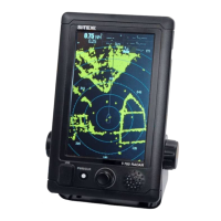
SP120C - Control Display Unit
• Steering control system for 4.0m -
16m vessels;
• ‘Virtual Rudder Feedback’ feature,
where no RFU requires to be
installed.
• 3 Control Modes – Manual Mode,
Auto Mode and GPS mode
• Live indication for ‘Steering mode’,
‘Position & Waypoint Info’, ‘Heading’,
‘Course to Steer’, ‘Rudder angle’,
‘System Voltage’ and ‘Drive Current’
• Supports all current NMEA-0183
interface standards;
• Heading: HDG, HDT, THS, HDM/
ROT & COG
• GPS: APA, APB, XTE, BOD, BWC &
RTR *for GPS steering mode
• GLL, RMC, SOG, VTG *for visual
indication and assisting AUTOPILOT
control
•30cmy-leadfordrivemotorand
power connections
• 6 pin LTW connectors for Compass
and Rudder/NMEA-0183 interfaces
• Power: 12-24 Volts DC (Up to 29V
During Charging)
• Drive output up to 35A. *If current
exceeds 35A, the drive output is
inhibited.
• Software controlled rudder limits,
inhibits drive control at each
mechanical limit.
• Additional auto switching fail
safes, in case of failure of RFU or
E-compass;
• If RFU fails, the system will
revert to Non-RFU mode
automatically.
• If a GPS system is connected
and the standard supplied
E-Compass fails, the SP120C
system will automatically revert
to GPS ‘COG’ mode for heading
reference.