4 of 34
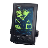
SI-TEX Marine Electronics - SP120C Color Autopilot
Overview
Standard Equipment
• SP120C CDU ‘Control Display Unit’
• ELECOM - electronic compass /
e-compass
• RFUS - rudder feedback unit
(optional)
Additional Equipment Required
(not standard supply)
1. Drive motor – to allow the
SP120C to control the vessels
steering system.
• Hydraulic steering systems with
a helm pump and ram will require
one of the following;
• Reversing hydraulic motor/
pump-set, tapped into the
existing hydraulic steering
system or;
• A constant running hydraulic
pump with direction control
solenoids.
A mechanical steering system will
require;
• a reversing mechanical drive,
connected to the existing
steering ram mechanism.
2. Termination hardware;
• Terminal blocks (suitable for
0.75mm
2
and 2.5mm
2
cables)
• Circuit breaker / switch (15A
rated)
• Wiring extension cables / ferrules
/ crimp lugs & related crimp tools
• 2c x 2.5mm
2
for extending motor
and power cables (larger for long
cable runs)
• 1 pair 0.75mm
2
for each nmea
interface cable
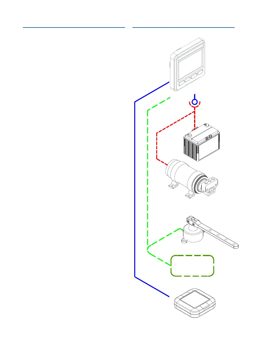
System Block Diagram
12 OR 24 VDC
BATTERY
*CUSTOMER
SUPPLIED
AUTOPILOT
DRIVE UNIT
*CUSTOMER
SUPPLIED
PILOT CONTROL
DISPLAY UNIT
ELECTRONIC
COMPASS
RUDDER
FEEDBACK
UNIT
*OPTIONAL
GPS (NMEA I/F)
*CUSTOMER
SUPPLIED
OPTIONAL
10m SUPPLIED CABLE
30CM FLYLEAD
FOR BATTERY
& MOTOR
CONNECTIONS
CUSTOMER
SUPPLIED
CABLES & TERMINALS
5m SUPPLIED CABLE