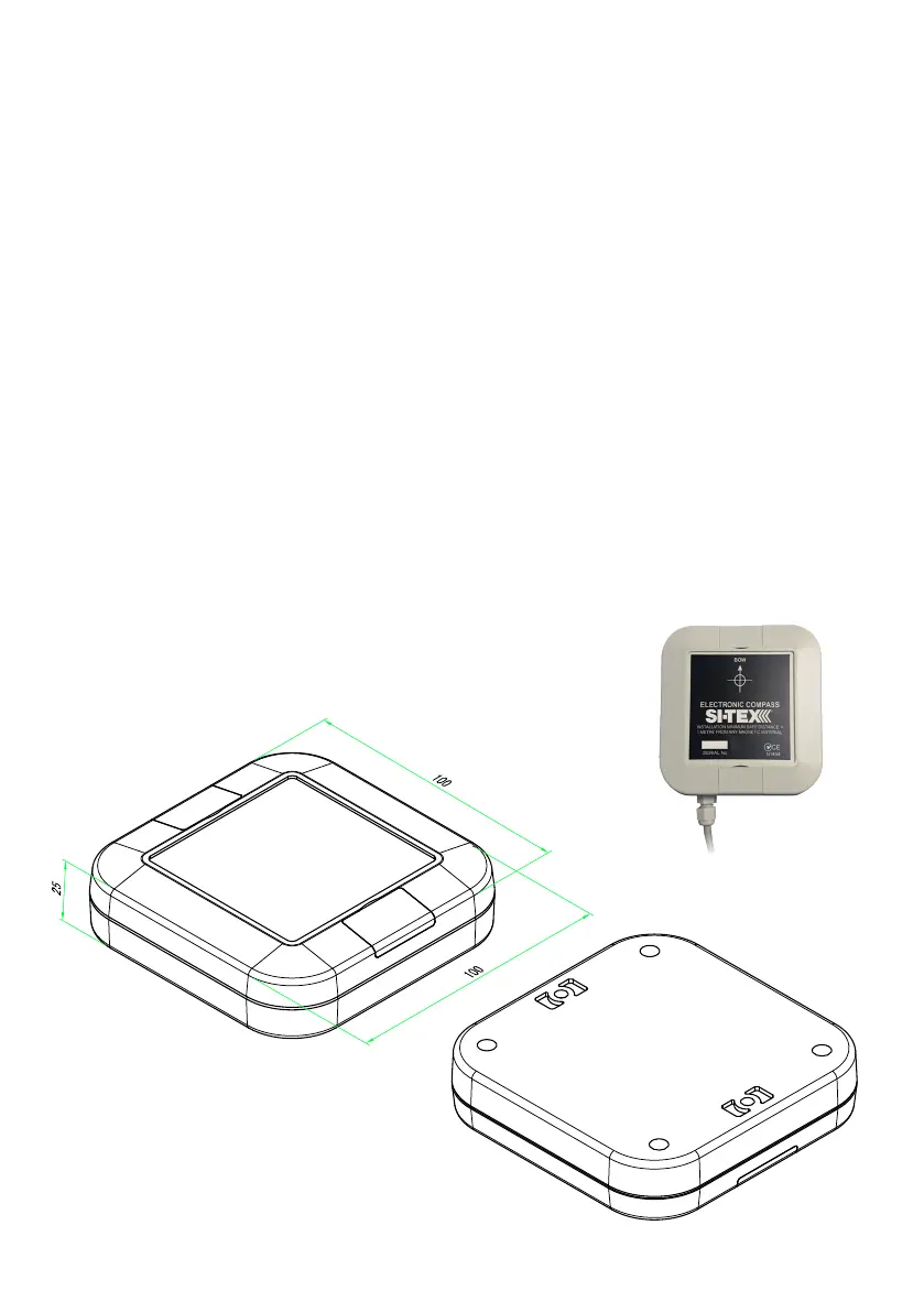
7 of 34SI-TEX Marine Electronics - SP120C Color Autopilot
• Solid state electronics with tilt and
roll compensation up to 35degrees.
E-Compass Installation Guide:
• IMPORTANT! The compass must
bettedinanareaatleast1meter
away from steel objects.
• Avoid positions near radios,
speakers, aerials, antenna cables or
any other current carrying cables.
• Select a dry position free from
magnetic interference.
•Ifsystemisttedtoasteelhull
vessel, the compass must be
mounted at least 1m above the steel
structure on a non-magnetic post or
bracket (aluminium and wood are
good options in this case)
• A lower / aft mounted position along
the centre of the hull is preferred, to
reducetheinuenceofvesselroll
and pitch.
• Check other side of bulkheads and
deck heads for magnetic interfering
type objects before mounting.
• Mount the compass horizontally
with the arrow (bow) pointing to the
front of the vessel, preferably on a
stainless steel, wooden or plastic
bracket.
• Use non-magnetic screws to mount
the compass unit (316 grade
stainless steel)
•Theunitmustbemountedonaat
horizontal surface.
• Before selecting the E-compass
installation position, it is good to
test the installation position is free
from interference by checking the
location with a portable magnetic
compass.
E-Compass Dimensions