22 GMS815P-PS-2G/-3G · Supplementary Operating Instructions · 8016234 V2.0 · © SICK AG
Installation
Subject to change without notice
3.8 Signal connections (I/O) in the gas analyzer enclosure
Only valid for Enclosure GMS815P-PS-3G without interface box
3.8.1 Opening the gas analyzer enclosure
1 Loosen both screws of the top enclosure door (suitable wrench in scope of delivery).
2 Open the top enclosure door.
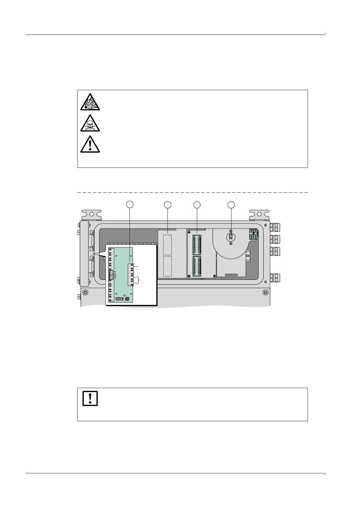
Fig. 4 Signal connections in the gas analyzer enclosure
3.8.2
Installing signal cables on the gas analyzer enclosure
▸
Lead the signal cables into the gas analyzer enclosure through a free cable inlet.
▸
Lead the signal cables out of the potentially explosive atmosphere and connect some-
where outside the potentially explosive atmosphere.
WARNING: Health risks
Before opening the enclosure:
▸
Interrupt every gas feed to the GMS800 apart from the purge gas feed
(when present).
▸
Switch the mains supply to the GMS800 off at an external source.
▸
Separate the GMS800 from all external voltages (e.g. signal lines). Excep-
tion: Connections to intrinsically safe power circuits can remain connected.
▸
If the GMS800 measures gases dangerous to health and it is not sure
whether the internal gas paths are gas-tight: Take protective measures
against escaping gas (e.g. breathing protection, suctioning off).
X5
X7
X4
X3
X5
X3
X4
X2
Ethernet
RS 485/
ext. I/O
1 Internal mains switch (for Service only)
2 I/O module (signal connections)
3 Second I/O module (option); alternatively: Intrinsically safe signal connections (→ p. 24, §3.9)
4Interfaces
13
4
2
▸
Use cables with outer diameter 6...14 mm for the cable inlets of the gas
analyzer enclosure.
▸
Use suitable cables (→ p. 18, 3.4.1).
▸
Seal cable inlets correctly after installation (→ p. 18, 3.4.2).

 Loading...


