3
Optical axis, receiver
4
Optical axis, sender
5
Cable
6
LED indicator yellow: Status of received
light beam
7
LED indicator green: Supply voltage
active
8
Potentiometer: sensing range
3
Optical axis, receiver
4
Optical axis, sender
5
Connector, M8
6
LED indicator yellow: Status of received
light beam
7
LED indicator green: Supply voltage
active
8
Potentiometer: sensing range
4 Mounting
Mount the sensor using a suitable mounting bracket (see the SICK range of acces‐
sories).
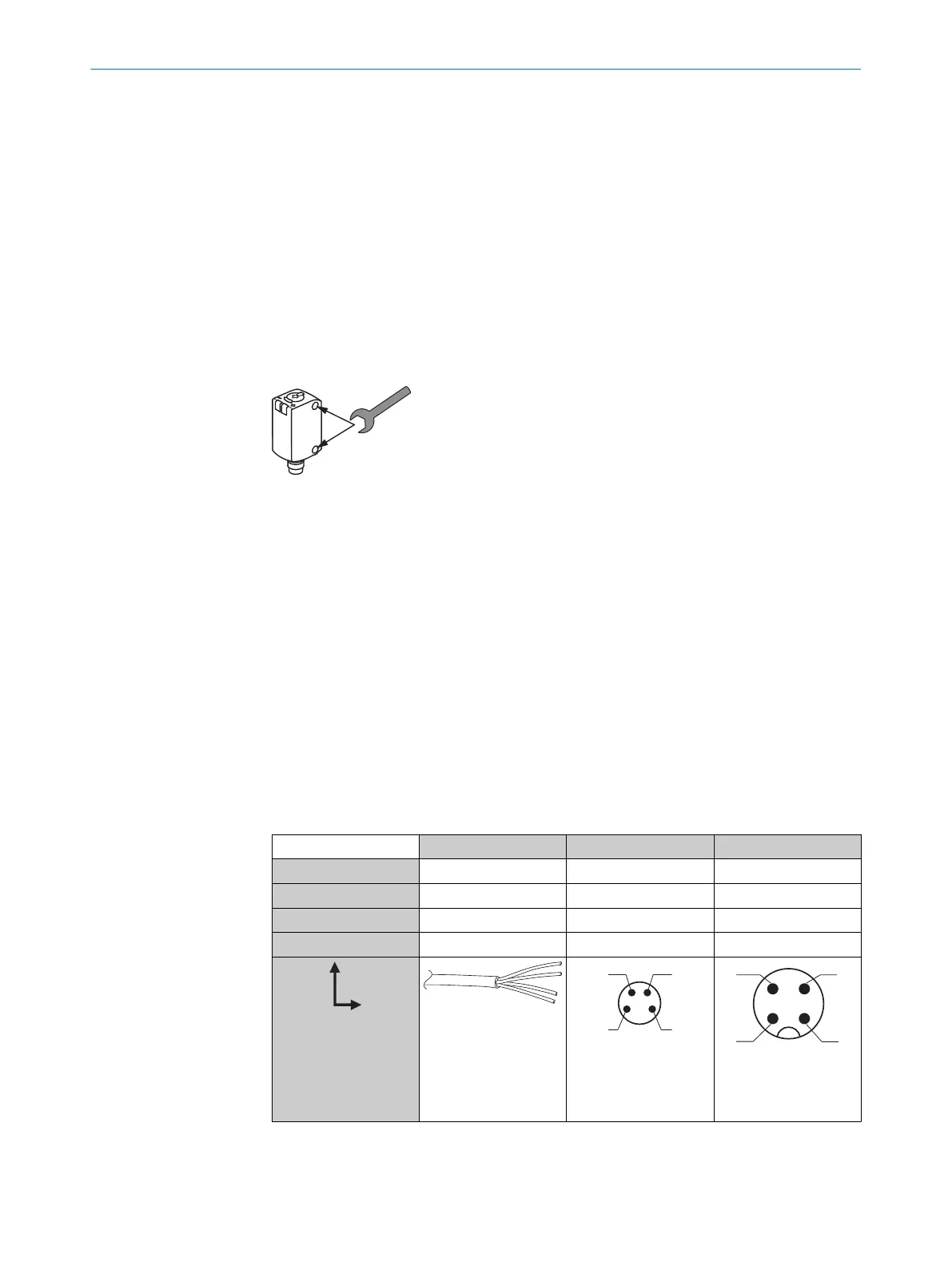
5 Electrical installation
The sensors must be connected in a voltage-free state (U
V
= 0 V). The following informa‐
tion must be observed, depending on the connection type:
– Male connector connection: pin assignment
– Cable: wire color
Only apply voltage/switch on the voltage supply (U
V
> 0 V) once all electrical connec‐
tions have been established. The green LED indicator lights up on the sensor.
Explanations of the connection diagram (Tables 2 and 3):
Q / Q = switching outputs
n. c. = not connected
DC: 10... 30 V DC, see „Technical specifications“, page 11
Table 1: DC
GTE6- x24xxV x44xxV x74xxV
1 + (L+) + (L+) + (L+)
2
Q Q Q
3 - (M) - (M) - (M)
4 Q Q Q
1= brn
2 = wht
3 = blu
4 = blk
0.14 mm
2
AWG26
4 MOUNTING
6
8021850 | SICK
Subject to change without notice

 Loading...


