Explicaciones del diagrama de conexión (tablas 2 y 3):
Q / Q = salidas conmutadas
n. c. = no conectado
CC: 10... 30 V CC, véase „Especificaciones técnicas“, página 67
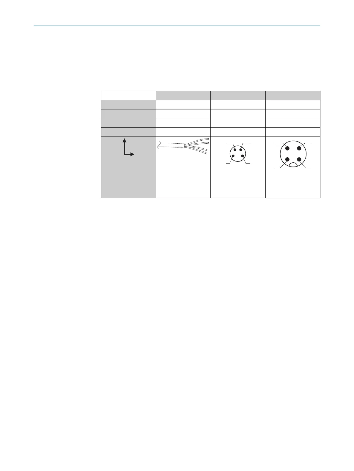
Tabla 21: DC
GTE6- x24xxV x44xxV x74xxV
1 + (L+) + (L+) + (L+)
2
Q Q Q
3 - (M) - (M) - (M)
4 Q Q Q
1= brn
2 = wht
3 = blu
4 = blk
0.14 mm
2
AWG26
INSTALACIÓN ELÉCTRICA 55
8021850 | SICK
Subject to change without notice
61

 Loading...


