INSTALLATION 4
8024534 / 16UW / 2020-02-26 Operating Instructions | InspectorP Rack Fine Positioning 19
Subject to change without notice
4.2.2 Mounting procedure
The device is delivered with pre-mounted illumination, pre-focused optics, pre-installed
software and pre-configured defaults. This enables quick and easy commissioning.
The optics are already pre-focused at a distance which is suitable for most applica-
tions. It might be necessary to adjust the focus position in rare cases, see
Figure 8:
Manual focus screw, page 24.
The procedure for mounting the device is divided into the following steps:
•
Mount the device with a view to the positioning mark
•
Connect the device to interfaces and supply voltage
•
Align the device using the laser alignment aid
4.2.3 Mounting device
Install the device to the mechanics with the bracket so that the device points vertically
to the positioning mark on the rack.
It should be mounted so that it is exposed to as little shock and vibration as
possible. Ensure that the position of the device is not moved by vibrations during
After switching on the supply voltage, the Continuous measurement parameter in the
device is activated by default. The device immediately goes into measurement mode.
Press the arrow button to switch the laser alignment aid on and off. The laser
alignment aid helps align the device. The device projects two red laser points on the
rack, signaling the viewing direction of the camera. The center of the image is between
the two points. Align the device so that the positioning mark on the rack is between
the two laser points and is therefore in the center of the image.
In a combined application with single and double deep racks, first align the device on
the single deep rack. Then adjust the position of the device for the double deep rack, if
applicable.
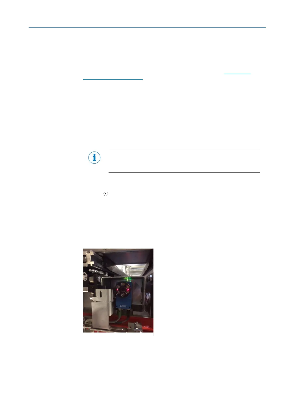
6: Mounting example