Avoiding any potential difference between load and protective device
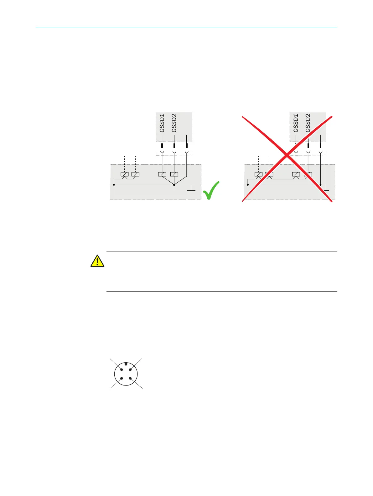
If y
ou connect loads to the output signal switching devices (switching outputs) that then
also switch if controlled with negative voltage (e.g., electro-mechanical contactor with‐
out reverse polarity protection diode), you must connect the 0 V connections of these
loads and those of the corresponding protective device separately and also directly to
the same 0 V terminal strip. In the event of a fault, this is the only way to ensure that
there can be no potential difference between the 0 V connections of the loads and
those of the corresponding protective device.
Figure 11: No potential difference between load and protective device
6.2 Notes on cULus
Important information
DANGER
Ris
k of burns from hot housing
b
Take measures to make sure the safety switch cannot be touched during opera‐
tion.
For use according to the requirements of UL 60947-5-2, the following conditions must
also be me
t:
•
The voltage supply must correspond to Class 2 in accordance with UL 508
•
Voltage supply U
v
secured with 1 A fuse
6.3 System connection (M12, 4-pin)
Figure 12: System connection pin assignment (male connector)
ELECTRICAL INSTALLATION 6
8023341/17AZ/2020-03-24 | SICK O P E R A T I N G I N S T R U C T I O N S | IME2S, IQB2S
19
Subject to change without notice