18
8025999/V1-0/2021-02 | SICKO P E R A T I N G I N S T R U C T I O N S | MICS3/OS3 electr. protection hood
Subject to change without notice
4 INSTALLATION
Observe scan plane, see also dimensional drawing Fig. 6/page 15.
4.3 Installation process
Provide tools for the screw type used.
▸ Loosed knurled screws on the protection hood and remove hood.
▸ Mount protection hood mechanism to the support unit (M8 screws).
▸ Check the mobility of the protection hood mechanism by hand (up and down move-
ment).
▸ Mount safety laser scanner to mounting kit 1a.
Observe the installation instructions in the corresponding SICK operating instructions.
▸ Seal unused connections with sealing caps.
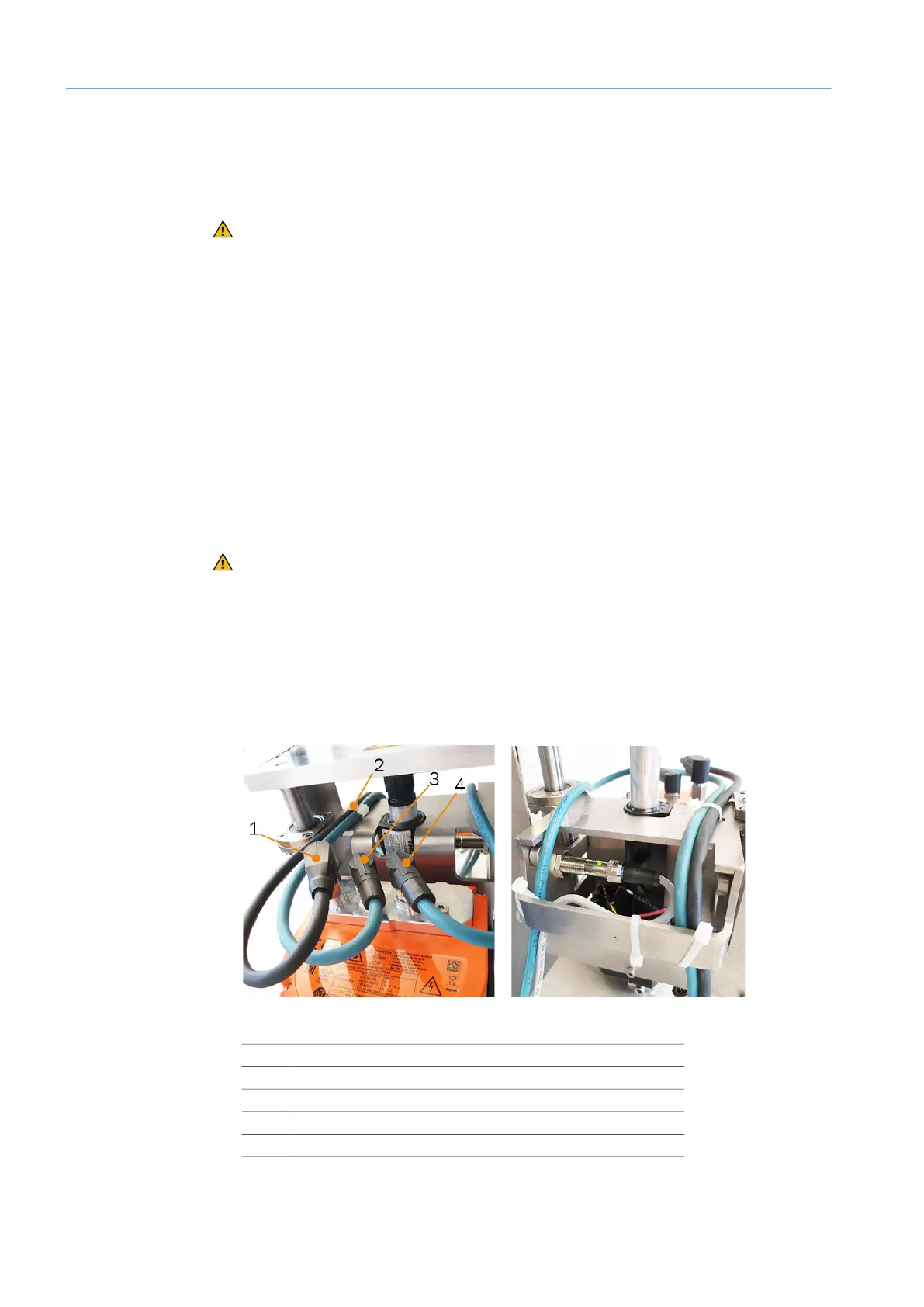
▸ Connect the cables to the safety laser scanner. Observe cable routing.
▸ For tightening torque of plug connector and protective caps, see the laser scanner oper-
ating instructions.
Fig. 11: Safety laser scanner connecting cables and cable routing to the rear
CAUTION Hazard due to hand injuries caused by crushing
▸ During the entire installation phase, the MICS3/OS3 electr. protection hood is
not connected to the control and is de-energized.
Note
Installation sequence:
▸ Mount the protection hood without safety laser scanner to the support unit.
▸ Mount safety laser scanner to the protection hood.
CAUTION Hazard due to hand injuries caused by crushing
▸ Wear safety gloves.
Legend
1
Voltage supply XD1
2
Cable tie for fixing cables
3
Ethernet XF1
4
Ethernet XF2