20
8025999/V1-0/2021-02 | SICKO P E R A T I N G I N S T R U C T I O N S | MICS3/OS3 electr. protection hood
Subject to change without notice
4 INSTALLATION
4.4.1 Contact assignment
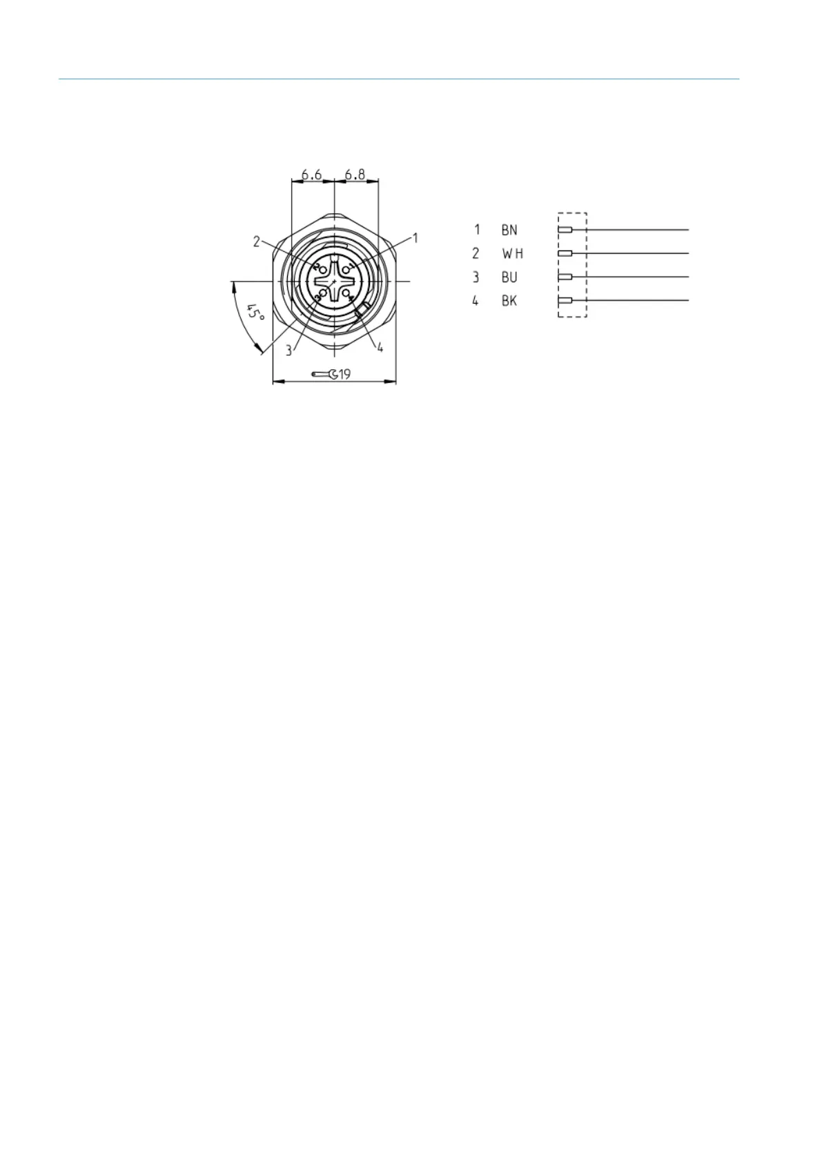
Fig. 13: M12 male connector pin arrangement - circuit diagram (contact assignment)
● The actuator motor is connected to pin 1 and 2.
● Pin 1 = yellow motor connection brown connecting cable
● Pin 2 = red motor connection white connecting cable