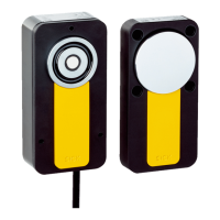
Using other safety switches
NOTE
In a c
ascade, other safety switches within the cascade can also be used via special T-
connectors as long as the connections are structured as follows:
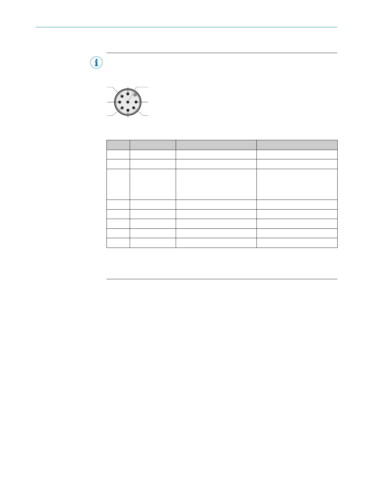
Table 3: Device connection pin assignment (male connector, M12, 8-pin, A-coded)
Pin Wire color
1)
Designation Description
1 White – –
2)
2 Brown +24 V DC Safety switch voltage supply
3 Green N. c.
or
+24 V DC
Not connected
or
V
oltage supply for locking device
3)
4 Yellow In 2 OSSD 2 input
5 Gray OSSD 1 OSSD 1 output
6 Pink OSSD 2 OSSD 2 output
7 Blue 0 V 0 V DC voltage supply
8 Red In 1 OSSD 1 input
1)
Applies to the extension cables recommended as accessories.
2)
Pin 1 is not assigned on T-connector. Safety switch signals to pin 1 are not relevant for the cascade (see
figure 18).
3)
The locking device must function in accordance with the power to lock principle.
Additional voltage supply
T
he voltage drop in the cascade must be checked so that the defined minimum voltage
is still applied to each safety switch. If the defined minimum voltage is no longer
applied to a safety switch, a node for voltage supply must be integrated. The node for
voltage supply must be integrated in the direction of the safe evaluation unit, as close
as possible to the relevant switch in the cascade.
Number of safety switches
The maximum number of safety switches depends on the following factors:
•
Applied supply voltage
•
Length of cables used
•
Cable cross-section of cables used
•
Load current
•
Nodes for voltage supply
•
Required performance level (see "Technical data", page 34)
The number of safety switches in a cascade influences the response time of the system
(see "Technical data", page 34).
The maximum number of safety switches in a cascade changes depending on the total
length of cable as follows:
4 P
ROJECT PLANNING
18
O P E R A T I N G I N S T R U C T I O N S | MLP1 8020169/ZJN1/2018-03-21 | SICK
Subject to change without notice