1
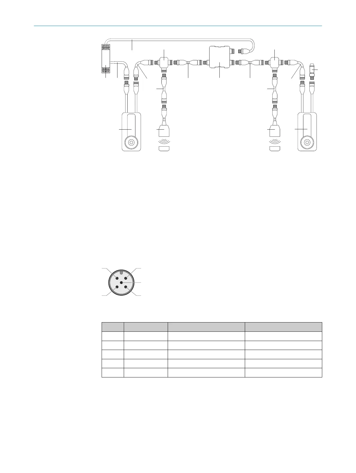
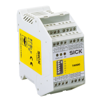
Safe evaluation unit
2
Connecting cable, M12, 5-pin
3
Connection cable, M12, 5-pin
4
End connector
5
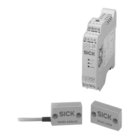
MLP1 safety switch
6
T-connector
7
Connection cable, M12, 8-pin
8
Other safety switch, M12, 8-pin
9
Nodes for voltage supply
Cascade connection (M12, 5-pin)
T
he 5-pin male connector of the last safety switch or T-connector upstream of the safe
evaluation unit is the interface between the cascade and the safe evaluation unit.
Figure 13: Cascade connection (M12, 5-pin, A-coded, male connector)
T
able 10: Device connection pin assignment (male connector, M12, 5-pin, A-coded)
Pin Wire color
1)
Designation Description
1 Brown In +24 V DC Safety switch voltage supply
2 White OSSD 1 OSSD 1 output
3 Blue 0 V 0 V DC voltage supply
4 Black OSSD 2 OSSD 2 output
5 Gray In +24 V DC Locking solenoid voltage supply
1)
Applies to the extension cables recommended as accessories.
ELECTRICAL INSTALLATION 6
8020169/ZJN1/2018-03-21 | SICK O P E R A T I N G I N S T R U C T I O N S | MLP1
29
Subject to change without notice