3
Connection cable, M12, 5-pin
4
End connector
5
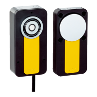
MLP1 safety switch (M12, 8-pin)
6
T-connector
7
Connection cable, M12, 8-pin
8
Other safety switch, M12, 8-pin
NOTE
In a c
ascade, other safety switches within the cascade can also be used via special T-
connectors as long as the connections are structured as follows:
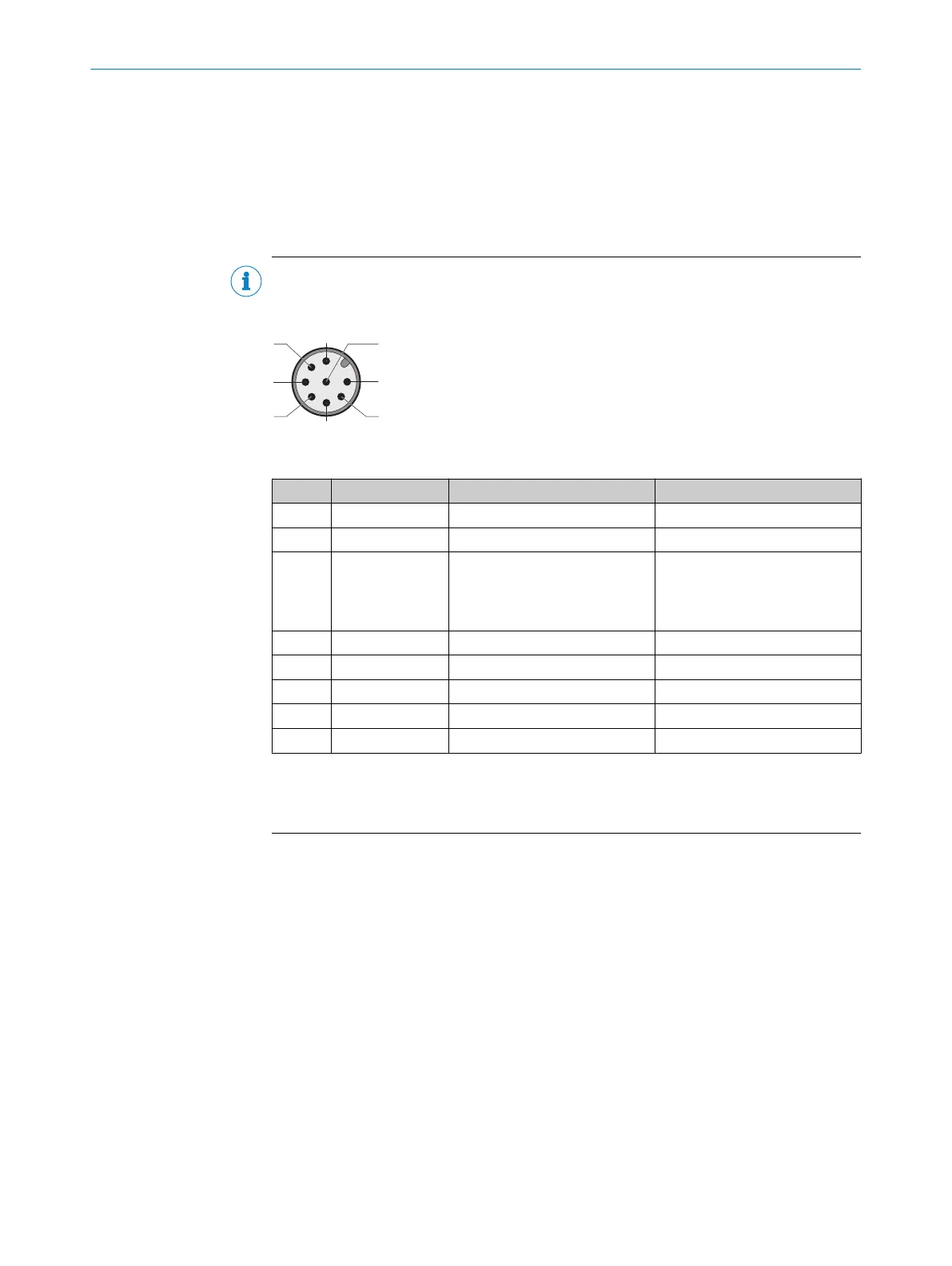
Table 9: Device connection pin assignment (male connector, M12, 8-pin, A-coded)
Pin Wire color
1)
Designation Description
1 White – –
2)
2 Brown +24 V DC Safety switch voltage supply
3 Green N. c.
or
+24 V DC
Not connected
or
V
oltage supply for locking device
3)
4 Yellow In 2 OSSD 2 input
5 Gray OSSD 1 OSSD 1 output
6 Pink OSSD 2 OSSD 2 output
7 Blue 0 V 0 V DC voltage supply
8 Red In 1 OSSD 1 input
1)
Applies to the extension cables recommended as accessories.
2)
Pin 1 is not assigned on T-connector. Safety switch signals to pin 1 are not relevant for the cascade (see
figure 18).
3)
The locking device must function in accordance with the power to lock principle.
Combining connection methods as desired
T
he various connection methods can be combined within a cascade as desired.
6 ELE
CTRICAL INSTALLATION
28
O P E R A T I N G I N S T R U C T I O N S | MLP1 8020169/ZJN1/2018-03-21 | SICK
Subject to change without notice