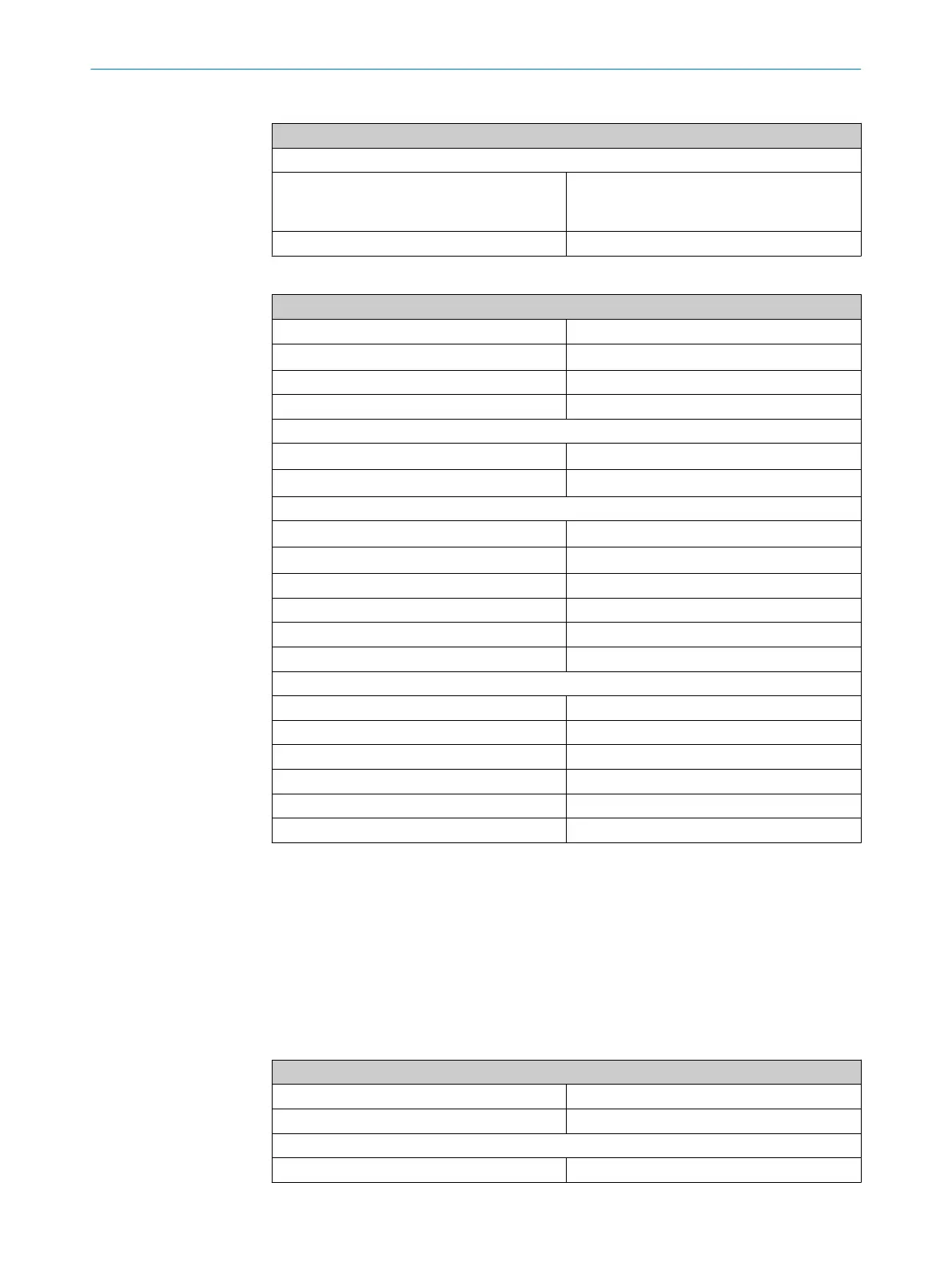
Table 15: Interfaces of variant with 1 × M12 plug connector, 8-pin
Interfaces of variant with 1 × M12 plug connector, 8-pin
System connection
Voltage supply
L
ocal inputs and outputs
Male connector, M12, 8-pin, A-coded (common
plug connector for voltage supply as well as
inputs and outputs)
Length of connecting cable 150 mm
Table 16: Electrical data
Electrical data
OSSD pairs 1
Rated impulse withstand voltage U
im
p
1,500 V
Pollution degree 3 (external, according to EN 60947-1)
Power-up delay (after supply voltage applied)
1)
2.5 s
Supply voltage when an individual safety switch is connected
Supply voltage V
v
sensor 24 V DC (19.2 V ... 28.8 V)
Supply voltage V
v
ma
gnet 24 V DC (19.2 V ... 28.8 V)
Supply voltage when an cascade is connected
Supply voltage V
v
sensor 24 V DC (22.8 V ... 28.8 V)
Supply voltage V
v
ma
gnet 24 V DC (21.6 V ... 28.8 V)
Muting time when supply voltage is interrupted 4 ms
Rated insulation voltage Ui 32 V DC
Cable capacitance 400 nF (for Out A and Out B)
Device fuse 0.6 ... 1 A
Current consumption at 24 V
Locking device deactivated 50 mA
Locking device active 350 mA
Protection class III (EN 61140/IEC 61140)
Response time
2)
≤ 50 ms
3)
Release time
4)
≤ 100 ms
3)
Risk time
5)
≤ 100 ms
3)
1)
Once the supply voltage has been switched on, the OSSDs are in the OFF state during the time delay
be
fore availability. The time specified applies to one sensor; in a cascade, 0.1 s must be added per sen‐
sor.
2)
Response time for moving the OSSDs into the OFF state when the actuator is removed from the response
ar
ea or when the OSSD input signals go into the OFF state.
3)
In a cascade, the value is multiplied by the number of safety switches in the cascade.
4)
Response time for moving the OSSDs into the ON state when the actuator is detected by the sensor and
t
he OSSD input signals are in the ON state.
5)
The risk time is the time needed to detect internal and external faults. External errors affect the OSSDs
(shor
t-circuit to an OSSD and cross-circuit between the two OSSDs). At least one of the two OSSDs is
safely switched off during the risk time.
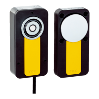
Table 17: Mechanical data
Dimensions (W x H x D)
Safety switch 120 mm x 60 mm x 38.5 mm
Actuator 120 mm x 60 mm x 20.5 mm
Material
Sensor housing Anodized aluminum
TECHNICAL DATA 11
8020169/ZJN1/2018-03-21 | SICK O P E R A T I N G I N S T R U C T I O N S | MLP1
35
Subject to change without notice