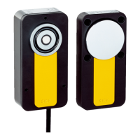
Dimensions (W x H x D)
Actuator housing Fiber-glass-reinforced PVC
Anchor plate Nickle-plated steel
Weight
Safety switch 510 g
Actuator 210 g
Table 18: Inputs
Inputs
Rated voltage 24 V DC
Switching current
ON state ≤ 5 mA
OFF state 0 mA
Switching voltage
ON state 19.2 V DC ... 28.8 V DC
OFF state 0 V DC ... 2 V DC
Table 19: Outputs
Outputs
2 OSSDs (Out 1 and Out 2) 2 x PNP, max. 100 mA, short-circuit protected
and o
verload-proof
1 Application diagnostic output (Aux) 25 mA max,
1)
shor
t-circuit protected (resistive
load)
Switching voltage (all outputs)
ON state 19.2 V DC ... 28.8 V DC
OFF state 0 V DC ... 2 V DC
Switching current (OSSDs)
ON state ≤ 100 mA
OFF state ≤ 500 µA
Test pulse duration (OSSDs) 300 µs
1)
A higher load affects the behavior of the status indicators, see "S
tatus indicators", page 11.
Table 20: Ambient data
Ambient data
Enclosure rating IP 67 (IEC 60529)
Ambient operating temperature –20 °C … +55 °C
Storage temperature -25 °C ... +70 °C
Relative humidity 50% at 70 °C (IEC 60947-5-2)
Vibration resistance 1 mm / 10 Hz ... 55 Hz (IEC 60068-2-6)
Shock resistance 30 g, 11 ms (IEC 60068-2-27)
EMC In accordance with IEC 61326-3-1, IEC
60947-5-2, IE
C 60947-5-3, and EN 300330
V2.1.1
Minimum distance between 2 safety switches Depending on alignment, see "Mounting sev‐
eral safety switches", page 20
11 TECHNICAL DATA
36
O P E R A T I N G I N S T R U C T I O N S | MLP1 8020169/ZJN1/2018-03-21 | SICK
Subject to change without notice