WINDOW
Input 2
Input 1
&
&
≥1 Output
Figure 25: Window Mode
HYSTERESIS
Input 2
Input 1
&
≥1
Q OutputR
S
Figure 26: Hysteresis Mode
NOTE
If no physical signal is applied to the external input or if a function other than “External
input” is selected for pin 2 configuration (ISDU 121), the status of the external input is
interpreted as logical 0.
Table 17: Smart Tasks – Timer
ISDU
Name
Data
type
Data
storage
Length Access
Default
value
Value/RangeIndex
Subin‐
dex
DEC HEX
1085
43D - Timer 1 mode
Uint Yes
1 byte
rw
0
0 = Deactivated
1 = T-on delay
2 = T-off delay
3 = T-on/T-off
4 = Pulses (one shot)
1086
43E - Timer 2 mode
1 byte
1087
43F - Time 1 setup 2bytes
1 1 ... 30,000ms
1088
440 - Time 2 setup
2bytes
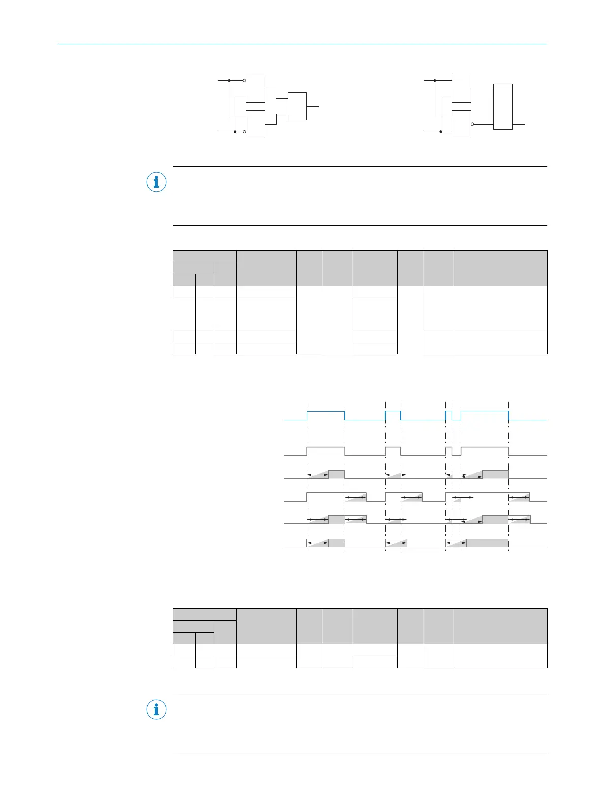
Timer 1/2 mode can be used to select various delay modes.
The relevant delay time is selected under Time 1/2 setup.
See the following graphic for details on how the different modes work.
t
t
t t t
t
t t t t
t t t
t
t
t t
Input signal Timer 1 / Timer 2
DEACTIVATED
Output signal Timer 1 / Timer 2
T-ON DELAY
Output signal Timer 1 / Timer 2
T-OFF DELAY
Output signal Timer 1 / Timer 2
T-ON / T-OFF DELAY
Output signal Timer 1 / Timer 2
IMPULSE (one shot)
Output signal Timer 1 / Timer 2
Figure 27: Timer 1/Timer 2
Table 18: Smart Tasks – Inverter
ISDU
Name
Data
type
Data
storage
Length Access
Default
value
Value/RangeIndex
Subin‐
dex
DEC HEX
1089
441 - Inverter 1
Uint Yes
1 byte
rw 0
0 = Not inverted
1 = Inverted
1090
442 - Inverter 2
1 byte
Inverter 1/2 inverts the logical condition of the timer 1/2 output signal.
NOTE
Inverting the Timer 1/2 output signal does not affect how the delay modes work.
Note that due to the inversion of the Timer 1/2 output signal, a set switch-on delay, for
example, can act like a switch-off delay.
OPERATION 9
8028041/2022-08-16 | SICK O P E R A T I N G I N S T R U C T I O N S | MPB10
47
Subject to change without notice